
Method for optimizing ammonia nitrogen mole ratio distribution of SCR denitration system

A technology of ammonia nitrogen molar ratio and denitrification, applied in separation methods, chemical instruments and methods, general control systems, etc., can solve problems such as air preheater blockage, high ammonia escape at the outlet, and uneven distribution of NOX concentration at the outlet

Active Publication Date: 2017-10-17
STATE GRID CORP OF CHINA +2
View PDF3 Cites 13 Cited by
  • Summary
  • Abstract
  • Description
  • Claims
  • Application Information

AI Technical Summary

Problems solved by technology

[0003] The technical problem to be solved in the present invention: Aiming at the above-mentioned problems in the prior art, provide a method that can effectively adjust the molar ratio distribution of ammonia nitrogen in the SCR denitrification system, and solve the problem of high ammonia escape at the outlet of the SCR denitrification system, uneven distribution of NOX concentration at the outlet, and the formation of ammonium bisulfate The method of optimizing the molar ratio distribution of ammonia nitrogen in the SCR denitrification system can effectively improve the molar ratio distribution of ammonia nitrogen in the upper layer of the first layer of catalyst. , improve the overall performance of the system, effectively reduce ammonia escape and ensure the efficient and stable operation of the air preheater on the premise of ensuring that NOX emissions meet the standards

Method used


Image

  • Method for optimizing ammonia nitrogen mole ratio distribution of SCR denitration system
  • Method for optimizing ammonia nitrogen mole ratio distribution of SCR denitration system
  • Method for optimizing ammonia nitrogen mole ratio distribution of SCR denitration system

Examples


Embodiment Construction

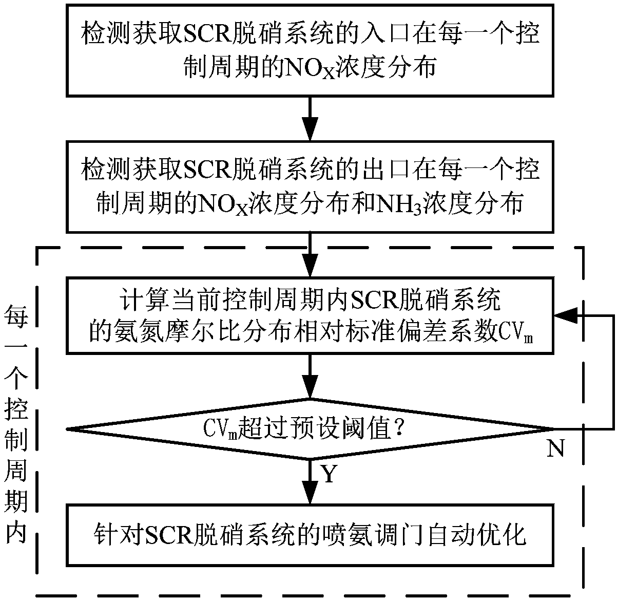
[0066] Such as figure 1 As shown, the implementation steps of the method for optimizing the molar ratio distribution of ammonia nitrogen in the SCR denitrification system in this embodiment include:

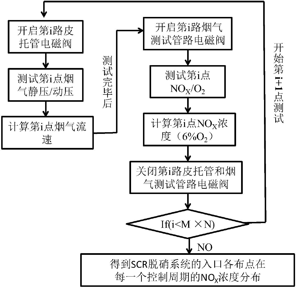
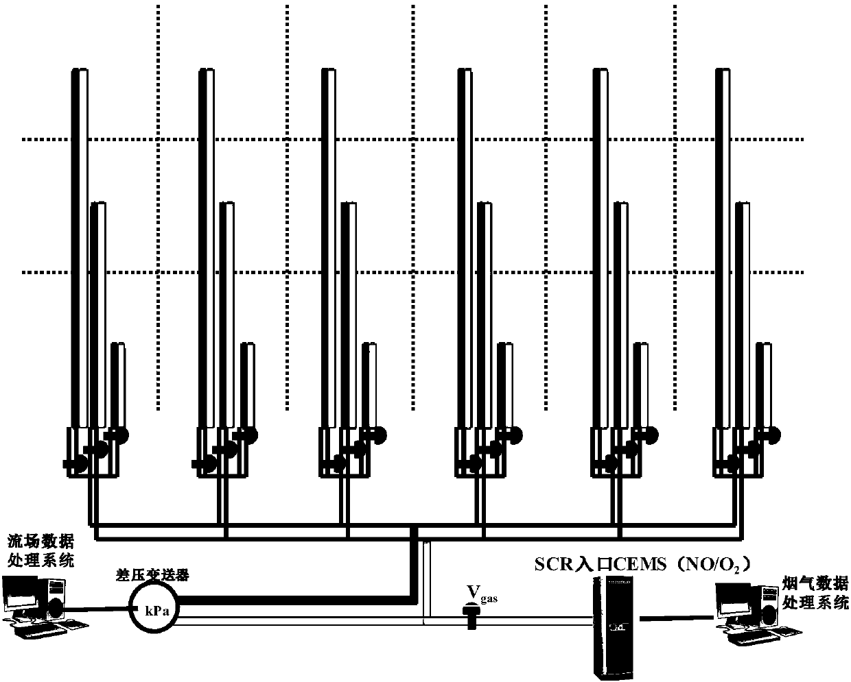
[0067] 1) Detection and acquisition of NO at the entrance of the SCR denitrification system in each control cycle X Concentration distribution;

[0068] 2) Detect and obtain NO at the outlet of the SCR denitrification system in each control cycle X Concentration distribution and NH 3 Concentration distribution;

[0069] 3) In each control cycle, the gate control area of ​​each branch pipe of the ammonia injection grid of the SCR denitrification system is regarded as a node, based on the NO in the outlet area corresponding to each node X Concentration distribution and NH 3 Concentration distribution, NO in inlet zone X Concentration distribution calculation of ammonia nitrogen molar ratio m at each node i , according to the ammonia-nitrogen molar ratio m of each node i Cal...


PUM


Abstract

The invention discloses a method for optimizing ammonia nitrogen mole ratio distribution of an SCR denitration system. The method comprises the following implementation steps: detecting to obtain NOX concentration distribution within each control period at the inlet of the SCR denitration system and NOX concentration distribution and NH3 concentration distribution within each control period at the outlet; within each control period, calculating an ammonia nitrogen mole ratio distribution relative standard deviation factor CVm of the SCR denitration system within the current control period, and while the ammonia nitrogen mole ratio distribution relative standard deviation factor CVm exceeds a preset threshold value, automatically optimizing in allusion to an ammonia spraying control valve of the SCR denitration system, ending and quitting the automatic optimization while the ammonia nitrogen mole ratio distribution relative standard deviation factor CVm does not exceed the preset threshold value. The method is capable of effectively regulating the ammonia nitrogen mole ratio distribution of the SCR denitration system, solving the problems that the outlet ammonia escape rate of the SCR denitration system is high, the outlet NOX concentration distribution is not uniform and the produced ammonium bisulfate blocks an air pre-heater, remarkably improving the flow field distribution in an SCR reactor, and effectively improving the availability ratio of the SCR denitration system.

Description

technical field [0001] The invention relates to the SCR denitrification technology of a coal-fired power plant, in particular to a method for optimizing the distribution of the ammonia nitrogen molar ratio in the SCR denitrification system. Background technique [0002] In selective catalytic reduction (SCR) systems, denitrification efficiency and outlet ammonia slip are the main performance characterization parameters. Due to the limited reserved space, the uneven distribution of the flue gas flow field generally exists in the denitrification upgrading of existing coal-fired power plants. There is a certain deviation in the NOX concentration, which is not conducive to the fine-tuning operation of the operator; at the same time, it also leads to high ammonia escape at the SCR outlet, and the generated ammonium bisulfate is likely to reduce the normal operation cycle of the air preheater. Therefore, how to realize a method to optimize the molar ratio distribution of ammonia ...

Claims


Application Information

Patent Timeline
IPC IPC(8): B01D53/90B01D53/56G01P5/165G01N33/00G05B13/02
CPCB01D53/8625B01D53/90B01D2251/2062G01N33/0036G01N33/0037G01N33/0054G01P5/165G05B13/024
Inventor 车垚陶莉周艳明张鸿
Owner STATE GRID CORP OF CHINA
Learn More