New energy electric vehicle

A technology of electric vehicles and new energy, applied in the direction of bumpers, etc., can solve the problems of frame deformation and poor side impact ability, and achieve the effect of good anti-side impact ability, not easy to deform, and increase the factors involved in energy absorption

Inactive Publication Date: 2019-05-03
周毅
View PDF5 Cites 0 Cited by
  • Summary
  • Abstract
  • Description
  • Claims
  • Application Information

AI Technical Summary

Problems solved by technology

[0010] The invention provides a new energy electric vehicle with good side impact resistance and the frame is not easily deformed during collision, which solves the problem that the existing new energy electric vehicle has poor side impact ability and easily causes frame deformation during collision

Method used


Image

  • New energy electric vehicle
  • New energy electric vehicle
  • New energy electric vehicle

Examples


Embodiment 1

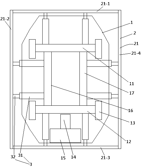
[0025] Embodiment one, see figure 1 , a new energy electric vehicle, comprising a car body 1, a safety ring 2 and an energy-absorbing cylinder 3. The vehicle body 1 is supported on a front axle 11 and a rear axle 12 through a suspension system. Both ends of the front axle 11 and the rear axle 12 are connected with wheels 13 . The vehicle body 1 is also provided with a drive motor 14 for driving the electric vehicle to walk and a power supply 15 for supplying power to the drive motor.

[0026] The safety ring 2 is wound around the vehicle body 1 and protrudes from the vehicle body 1 in the horizontal direction. The insurance ring 2 is composed of four bumpers 21 connected end to end in sequence, and the four bumpers 21 are respectively a front bumper 21-1, a left bumper 21-2, a rear bumper 21-3 and a right bumper 21-4 . A left longitudinal load-bearing beam 16 and a right longitudinal load-bearing beam 17 are connected between the front axle 11 and the rear axle 12 . The f...

Embodiment 2

[0032] Embodiment two, the difference with embodiment one is:

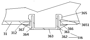
[0033] see Figure 4 , The inner peripheral surface of the circular inner tube 361 is provided with a guide vane 368 that guides the plug 36 to rotate when the fluid flows through the circular inner tube. The compression cylinder 31 is also provided with a support frame 38 . The support frame 38 is rotatably connected with the knife seat 39 of the circular tube structure through the plane bearing 381 . The knife seat 39 is connected with an annular knife body 391 . A limiting portion 392 is formed between the knife body 391 and the knife seat 39 . The cutter body 391 is provided with a cutting edge 393 . The cutting edge 393 is aligned with the base plate 363 . The outer diameter of the cutter body 391 is equal to the inner diameter of the circular inner tube 361 .

[0034] From the use process, if the plug 36 ejects, before the cutting edge 393 contacts with the base plate 363, the knife seat 39 is inserted...


PUM


Abstract

The invention relates to vehicles. A new energy electric vehicle comprises a vehicle body, vehicle axles and front, rear, left and right bumpers, wherein the front, rear, left and right bumpers surround the periphery of the vehicle body, and each bumper is connected with the corresponding vehicle axle together through at least two energy absorption cylinders; the energy absorption cylinders for connecting the left and right bumpers stretch out and draw back in the front-rear direction, and the energy absorption cylinders for connecting the front and rear bumpers stretch out and draw back in the left-right direction; and each energy absorption cylinder comprises a compression cylinder, a piston and a driving rod, wherein one end of each compression cylinder is closed, each piston is slidably connected in the corresponding compression cylinder in a sealed mode, each driving rod is connected with the corresponding piston through first connecting rods via the opening end of the compression cylinder, and piston rods extend out of the compression cylinders via the opening ends of the compression cylinders, each compression cylinder is provided with a jet hole, and a plug capable of being squeezed out is connected with each jet hole in a sealing mode. The new energy electric vehicle has the advantages that the side impact resistance is good, and a vehicle frame is not prone to generating deformation when being collided, and solves the problems that an existing new energy electric vehicle is poor in side impact resistance, and a vehicle frame is prone to being deformed when being collided.

Description

technical field [0001] The invention relates to automobiles, in particular to a new energy electric automobile. Background technique [0002] The bridge frame of the car is composed of the frame, the rear axle (drive axle) supporting the frame and the front axle of the car (also known as the front axle, which is the steering axle). Both ends of the drive axle and the front axle are connected to the wheels, and the frame passes through the suspension Attached to the frame. [0003] Initially, the engine (gasoline or diesel engine) was used as the core power, and the fuel was used as the power to realize the normal driving of the vehicle. However, fuel-powered vehicles will consume non-renewable energy (gasoline or diesel) as soon as the vehicle is started, and cause a considerable degree of pollution to the environment. [0004] 1. The characteristics of fuel (automobile) vehicles and the hazards of automobile exhaust [0005] 1. Automobile exhaust contains a large amount ...

Claims


Application Information

Patent Timeline
Patent Type & Authority Patents(China)
IPC IPC(8): B60R19/32B60R19/42
CPCB60R19/32B60R19/42
Inventor 周毅
Owner 周毅
Why Eureka
Try Eureka