
a buried lamp

A technology for underground lamps and lamp sockets, which is applied to lighting auxiliary devices, lighting and heating equipment, fixed lighting devices, etc., can solve problems such as deficiencies, and achieve the effects of strong adaptability, good heat dissipation effect, and adjustable light source angle.

Active Publication Date: 2019-08-27
余姚市新概念照明电器有限公司
View PDF5 Cites 0 Cited by
  • Summary
  • Abstract
  • Description
  • Claims
  • Application Information

AI Technical Summary

Problems solved by technology

Although the current buried lights can realize the lighting function, they are still insufficient in terms of heat dissipation and adjustment capabilities.

Method used


Image

  • a buried lamp
  • a buried lamp
  • a buried lamp

Examples


Embodiment 1

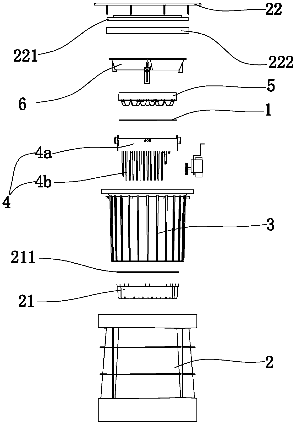
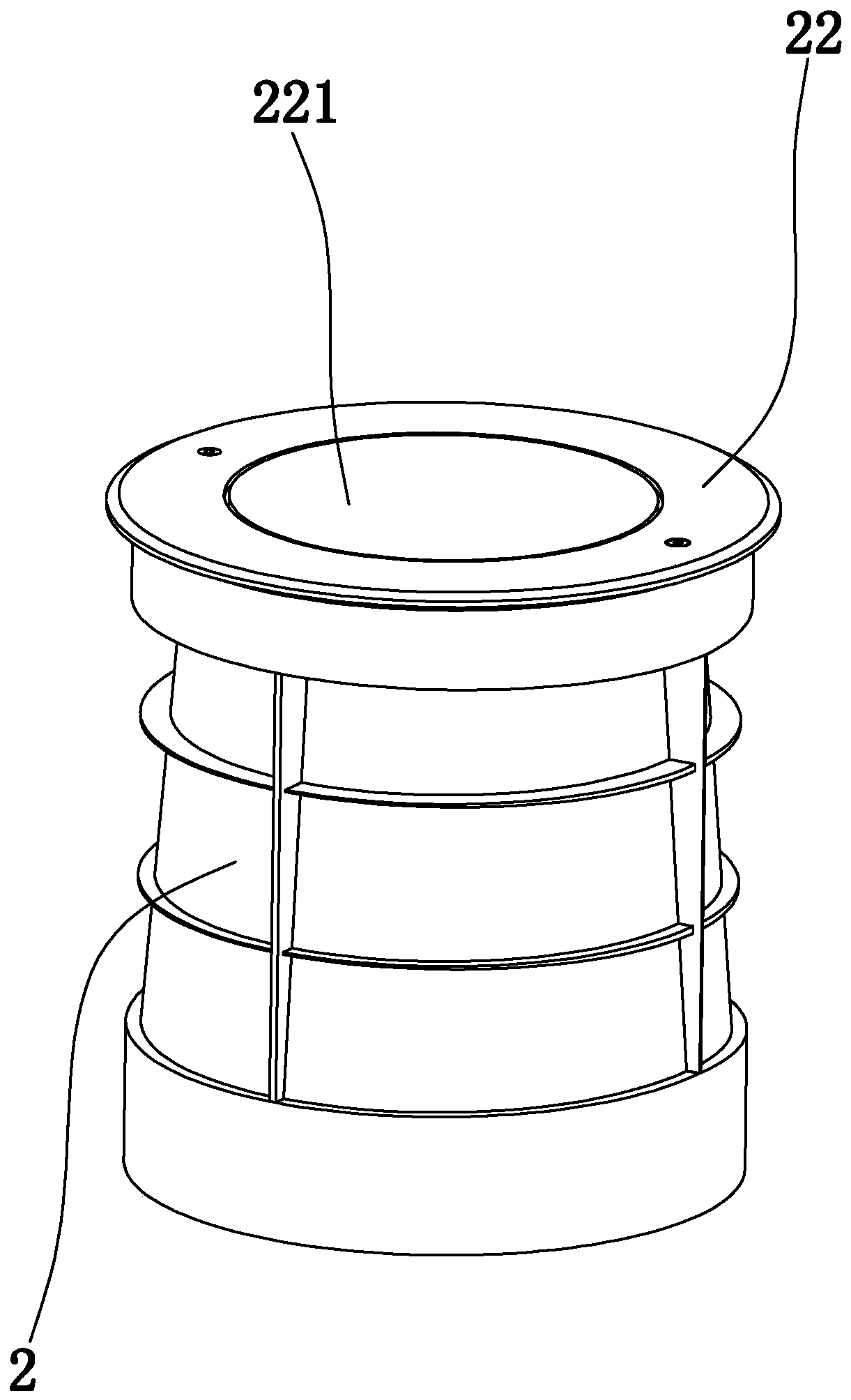
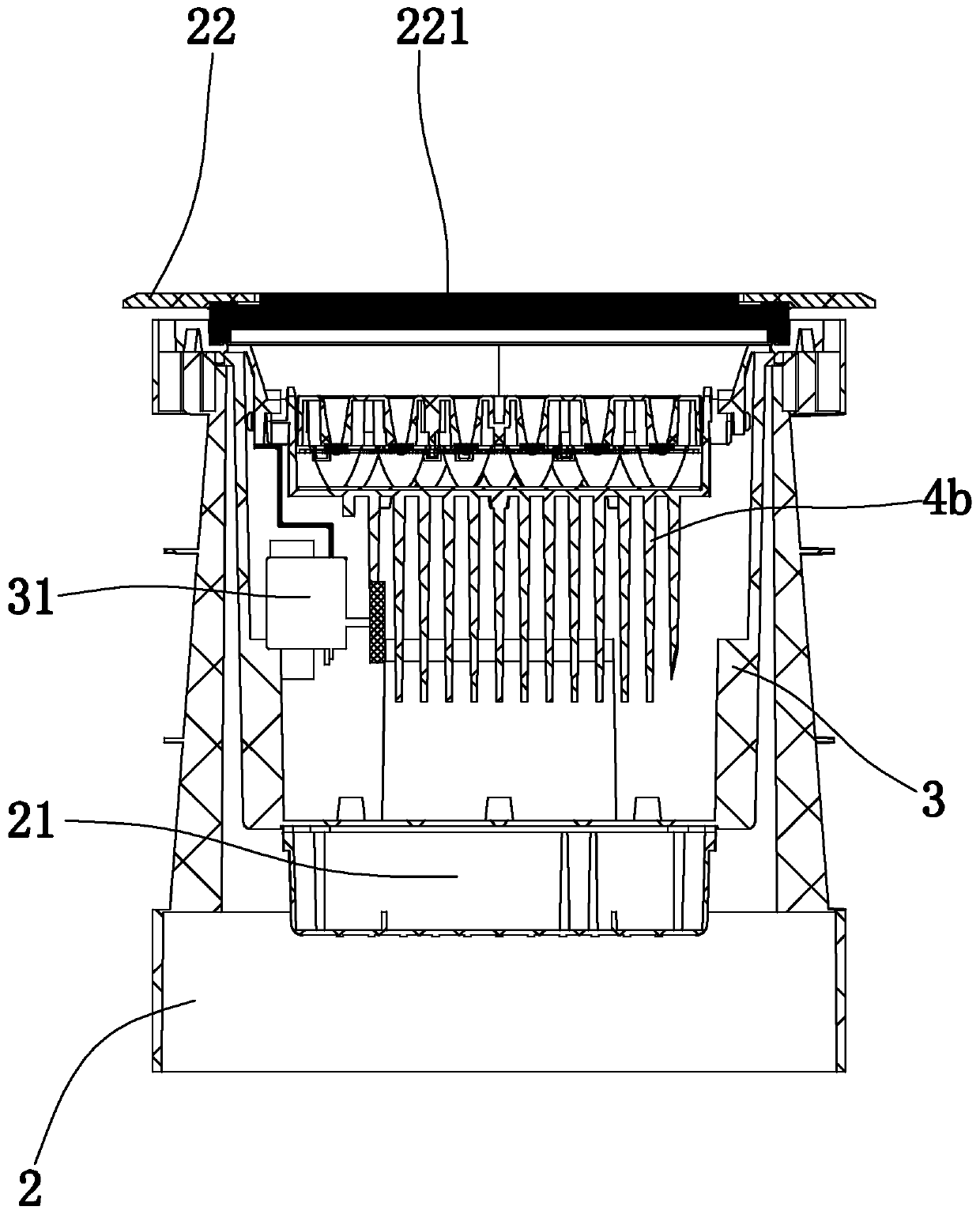
[0027] Example 1: Figure 1 to Figure 3 As shown in , a buried lamp includes an aluminum substrate 1 and a plurality of LED illuminants arranged on the aluminum substrate, and also includes

[0028] The pre-embedded outer cylinder 2, the bottom cover plate 21 arranged on the inner bottom of the pre-embedded outer cylinder and the top panel 22 arranged on the top of the pre-embedded outer cylinder. There is a radiator 4 and a condenser lens 5, the aluminum substrate is between the radiator and the condenser lens, all the illuminants are between the aluminum substrate and the condenser lens, the aluminum substrate is connected to the radiator, and the aluminum substrate is connected to the condenser lens;

[0029] The lamp holder tube is provided with a cooling bracket 6, and the cooling body is rotatably connected with the cooling bracket through a rotating shaft, and a motor 31 for driving the cooling body to rotate along the axis of the rotating shaft is arranged inside the ...

Embodiment 2

[0038] Embodiment 2: the basic structure and implementation mode of this embodiment are the same as embodiment 1, and its difference is, as Figure 4 to Figure 5 As shown in , the top panel is an annular plate, the top panel includes an outer ring plate 22a fixed to the lamp holder tube and an inner ring plate 22b that can move up and down relative to the outer ring plate, the outer ring plate is sleeved outside the inner ring plate, The central light-transmitting hole is set on the inner ring plate, the top plate is arranged horizontally, and the supporting ring edge plate 223 connected with the outer ring plate is arranged under the inner ring plate, and an annular sealed space is formed between the supporting ring edge plate and the inner ring plate. An inflatable sealing ring 22c arranged coaxially with the top panel is arranged in the annular sealed space, and a number of buffer cylinders 7 are arranged on the lamp holder cylinder, and buffer pistons 71 are arranged in the...


PUM


Abstract

The invention discloses an underground light which comprises an aluminium substrate, a plurality of LED luminophors arranged on the aluminium substrate, a pre-embedded outer barrel, a bottom cover plate arranged at the inner bottom of the pre-embedded outer barrel and a top panel arranged at the top of the pre-embedded outer barrel. A light holder barrel is arranged in the pre-embedded outer barrel; a radiator and a condensing lens are arranged in the light holder barrel; the aluminium substrate is placed between the radiator and the condensing lens; all the luminophors are placed between the aluminium substrate and the condensing lens; the aluminium substrate is connected with the radiator; and the aluminium substrate is connected with the condensing lens. A radiating support is arranged on the light holder barrel, the radiator is in rotating connection with the radiating support through a rotating shaft, and a motor used for driving the radiator to rotate is arranged in the light holder barrel. A glass panel is arranged on the top panel. The underground light has the beneficial effects of being capable of achieving lighting for people and objects, having light gathering capacity, and being good in radiating effect, adjustable in light source angle and high in adaptability.

Description

technical field [0001] The invention belongs to the technical field of lamps, in particular to a buried lamp. Background technique [0002] Buried lights are widely used in the field of lighting. Because they are buried in the ground for people and objects to illuminate, they are named buried lights. There are usually two kinds of buried light sources: ordinary light source and LED light source. The light source is also divided into monochrome and multi-color. The color of LED multi-color light source is more gorgeous. The lamp body is generally round, square, rectangular, arc and so on. Although the current buried lights can realize the function of illumination and lighting, they are still insufficient in terms of heat dissipation effect and adjustment ability. Contents of the invention [0003] The object of the present invention is to overcome the deficiencies in the prior art, and provide a buried lamp capable of illuminating people and objects, having light-gatherin...

Claims


Application Information

Patent Timeline
Patent Type & Authority Patents(China)
IPC IPC(8): F21S8/02F21V21/02F21V29/74F21V31/00F21V23/00F21V5/04F21V15/04F21Y115/10
Inventor 邵银明
Owner 余姚市新概念照明电器有限公司
Learn More