
Manufacturing method of color visible light-focusing line and its device

A production method and visible light technology, applied in optics, optical components, image duplicators, etc., can solve the problems of large volume and power consumption, large volume, large power consumption, unfavorable integration, etc., and achieve simple composition, low power consumption, and low cost. low effect

Inactive Publication Date: 2005-11-09
袁宁 +1
View PDF0 Cites 4 Cited by
  • Summary
  • Abstract
  • Description
  • Claims
  • Application Information

AI Technical Summary

Problems solved by technology

[0002] At present, there are many three-primary-color light-emitting devices, but most of them are composed of three-primary-color discrete components or three-primary-color high-power components, resulting in large volume and power consumption, which is neither convenient for portability nor integration. The degree of uniformity is different. To meet the requirements of producing colored visible light arrays, multiple sets of discrete components are required to form three primary color light emitting units, and the produced colored visible light arrays also have no light-gathering performance. The colored visible light row condenses light into a colored visible light condensing row, resulting in large volume and power consumption, and the generated colored visible light is not uniform. It is a problem to be solved that the colored visible light condensing row meets the specific requirements, and makes the three-primary-color light-emitting tube row and the condensing mirror row device miniaturized, and is easy to be integrated in other objects, and produces uniform colored visible light condensing lines.

Method used


Image

  • Manufacturing method of color visible light-focusing line and its device
  • Manufacturing method of color visible light-focusing line and its device
  • Manufacturing method of color visible light-focusing line and its device

Examples


Embodiment Construction

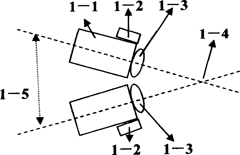
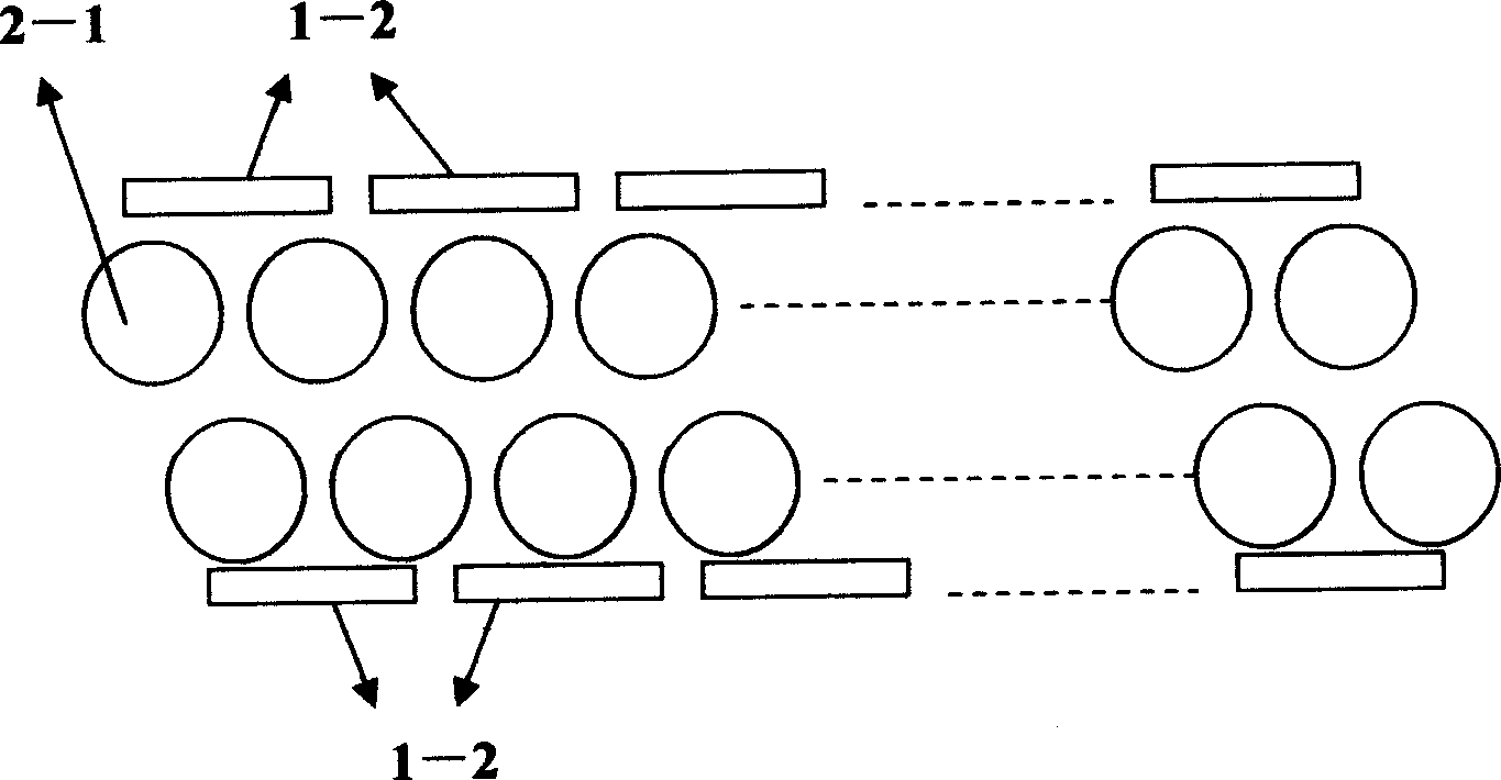
[0026]In the colored visible light condensing row device of the present invention, the three primary color light-emitting units are composed of three primary color high-brightness red, green, and blue semiconductor laser light-emitting tubes or three primary-color high-brightness red, green, and blue light-emitting diodes, and the three primary color light-emitting units are formed into a long strip according to certain rules to form three primary colors Light-emitting tube rows, and each of the three primary color light-emitting units is equipped with a condenser one-to-one, so that when the three primary color light-emitting tube rows emit light at the same time according to different color signals, a row of colored visible light rows is generated. After the colored visible light rows are focused by the condenser row, the focus The dots form a line consisting of colored focused spots to form a color video electrical signal converted into a colored visible light visible video p...


PUM


Abstract

This invention relates to a manufacturing method for visible light-gathering row. A new color visible light emitting unit of three primary colors or multiple primary colors generates color visible lights with their own focusing abilities. Each emitting light unit generates focusing points, which forms a continuous parallel line provided to a beam light mirror, beam light slit and a mirror arc three prism to be reflected by the prism to generate video images.

Description

technical field [0001] The invention relates to a manufacturing method and device for producing colored visible light rows and condensing the colored visible light rows into a focusing point row, in particular to a method and device for making a colored visible light concentrating row from three primary color light-emitting tube rows and condenser mirror rows. technical background [0002] At present, there are many three-primary-color light-emitting devices, but most of them are composed of three-primary-color discrete components or three-primary-color high-power components, resulting in large volume and power consumption, which is neither convenient for portability nor integration. The degree of uniformity is different. To meet the requirements of producing colored visible light arrays, multiple sets of discrete components are required to form three primary color light emitting units, and the produced colored visible light arrays also have no light-gathering performance. T...

Claims


Application Information

Patent Timeline
Patent Type & Authority Applications(China)
IPC IPC(8): H04N9/12
CPCH04N9/12
Inventor 袁宁张立
Owner 袁宁
Learn More