
Organic light-emitting display panel and production method thereof

By making a reflective cathode in the light-emitting area of ​​the OLED display panel and avoiding its presence in the non-light-emitting area, the problem of color purity reduction and color shift caused by light reflection in the bottom-emitting device is solved, and the display effect is improved.

Active Publication Date: 2017-10-17
WUHAN CHINA STAR OPTOELECTRONICS SEMICON DISPLAY TECH CO LTD
View PDF7 Cites 22 Cited by
  • Summary
  • Abstract
  • Description
  • Claims
  • Application Information

AI Technical Summary

Problems solved by technology

[0004] However, due to the increasing resolution of display screens and the denser arrangement of pixels, in bottom-emitting devices, part of the light emitted by the organic material of a sub-pixel will pass through the cathode of the non-luminous area. The reflection is emitted from the adjacent sub-pixels, resulting in a decrease in color purity and color shift, which in turn affects the display effect

Method used


Image

  • Organic light-emitting display panel and production method thereof
  • Organic light-emitting display panel and production method thereof
  • Organic light-emitting display panel and production method thereof

Examples


Embodiment 1

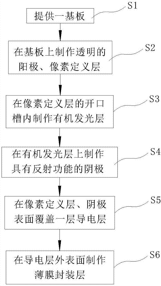
[0025] refer to figure 1 The bottom-emission organic light-emitting display panel of this embodiment includes a substrate 10, a transparent anode 20 located on the substrate 10, a pixel definition layer 30, an organic light-emitting layer 40, and several cathodes 50 with reflective functions. The pixel definition layer 30 is provided with A plurality of open grooves, one end of the open groove close to the substrate 10 is arranged on the anode 20, the organic light-emitting layer 40 is filled in the open groove, the cathode 50 is arranged on the organic light-emitting layer 40 and accommodated in one end of the open groove away from the substrate 10, each opening The two ends of the tank correspond to an anode 20 and an anode 20 respectively.

[0026] In order to realize that all the cathodes 50 are electrically connected to each other, so as to facilitate the transmission of electrical signals, a conductive layer 60 is formed on the surface of the cathode 50 in this embodimen...

Embodiment 2

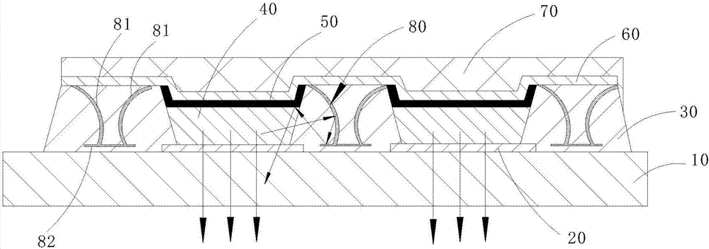
[0039] like image 3 As shown, the difference from Embodiment 1 is that the bottom emission organic light emitting display panel of this embodiment also has a reflector 80, and the reflector 80 is arranged in the pixel definition layer 30 for directing the incident light toward the adjacent organic light emitting display panel. The luminescent layer 40 is reflective.

[0040] The reflector 80 specifically includes a first reflective portion 81 whose reflective surface is a concave arc surface, the first reflective portion 81 is a rotating body, and a second reflective portion 82 covering the end face of the first reflective portion 81, the second reflective portion Edges 82 extend from the end surface of the first reflective portion 81 toward the surroundings. Part of the light emitted from the organic light-emitting layer 40 into the pixel definition layer 30 is reflected back to the organic light-emitting layer 40 by the first reflective portion 81, and part of the light is...

Embodiment 3

[0042] like Figure 4 As shown, the difference from Embodiment 2 is that the reflection member 80 of this embodiment includes a cylindrical reflection ring perpendicular to the substrate 10 . The reflective ring can reflect back the light emitted from the surrounding adjacent organic light-emitting layers 40 , preventing interference between adjacent pixels and improving the utilization rate of the light source.

[0043]In the bottom-emitting organic light-emitting display panel of the present invention, the cathode with reflection function is only fabricated in the light-emitting area, and the cathode with reflection function is not fabricated in the non-light-emitting area, which can effectively prevent the light emitted from the sub-pixel from interfering with adjacent pixels in the bottom light-emitting device. sub-pixels, thereby improving color purity and improving color cast.


PUM


Abstract

The invention discloses an organic light-emitting display panel. The organic light-emitting display panel comprises a substrate; transparent anodes, a pixel definition layer, organic light-emitting layers, and a plurality of cathodes having reflection functions, which are disposed on the substrate. The pixel definition layer is provided with a plurality of opening grooves, and the anodes are disposed on the ends of the opening grooves close to the substrate. The opening grooves are filled with organic light-emitting layers, and the cathodes are accommodated in the ends of the opening grooves away from the substrate. The invention also provides the production method of the organic light-emitting display panel. The organic light-emitting display panel is advantageous in that the cathodes having the reflection functions are disposed in the light-emitting areas, and the cathodes having the reflection functions are not disposed in the non-light-emitting areas, and interferences of light emitted by sub-pixels on adjacent sub-pixels in a light-emitting device are effectively prevented, and therefore color purity is improved, and a chromatic polarization phenomenon is improved.

Description

technical field [0001] The present invention relates to the field of organic light emitting display technology, in particular to an organic light emitting display panel and a manufacturing method thereof. Background technique [0002] OLED (Organic Light Emitting Diode, Organic Light Emitting Diode) display is a new generation of display. By making an organic film on the OLED substrate, the organic film is sandwiched between the cathode and the anode metal or conductive layer, and the voltage is applied to the two electrodes. Then the organic film will emit light. Compared with liquid crystal displays, OLED displays have many advantages such as self-illumination, fast response, wide viewing angle, and saturated colors. [0003] OLEDs are divided into two types: top-emitting and bottom-emitting. In bottom-emitting devices, the anode generally uses transparent conductive layers such as ITO, and the cathode generally uses metals with high reflectivity such as Al, Mg, and Ag. T...

Claims


Application Information

Patent Timeline
Patent Type & Authority Applications(China)
IPC IPC(8): H01L27/32H01L51/52H01L51/56
CPCH10K59/80523H10K59/878H10K59/122H10K50/805H10K50/813H10K50/822H10K50/826H10K50/856H10H20/856
Inventor 余威
Owner WUHAN CHINA STAR OPTOELECTRONICS SEMICON DISPLAY TECH CO LTD
Learn More