
Spring coiling machine and spring coiling process

A spring coiling machine and coiling spring technology, which is applied in the field of spring coiling machine and spring rolling process, can solve the problems of different bending arcs of springs, insufficient roundness of spring coils, and failure to meet the requirements of spring coiling standards, so as to meet production needs , to avoid the effect of uneven pressure

Active Publication Date: 2017-10-20
浙江裕荣弹簧有限公司
View PDF8 Cites 0 Cited by
  • Summary
  • Abstract
  • Description
  • Claims
  • Application Information

AI Technical Summary

Problems solved by technology

[0004] However, the upper guide wheel and the lower guide wheel are controlled by the upper guide wheel oil cylinder and the lower guide wheel oil cylinder respectively, and the driving forces of the two oil cylinders are different, which will cause the upper guide wheel and the lower guide wheel to act differently on the rolling spring. , resulting in different bending arcs of the rolled springs, making the spring rolls not round enough to meet the standard requirements of spring rolling

Method used


Image

  • Spring coiling machine and spring coiling process
  • Spring coiling machine and spring coiling process
  • Spring coiling machine and spring coiling process

Examples


Embodiment 1

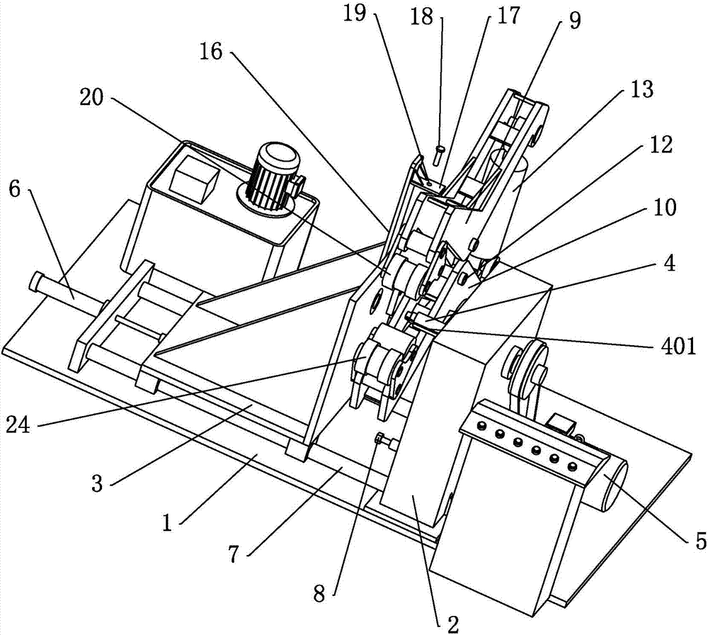
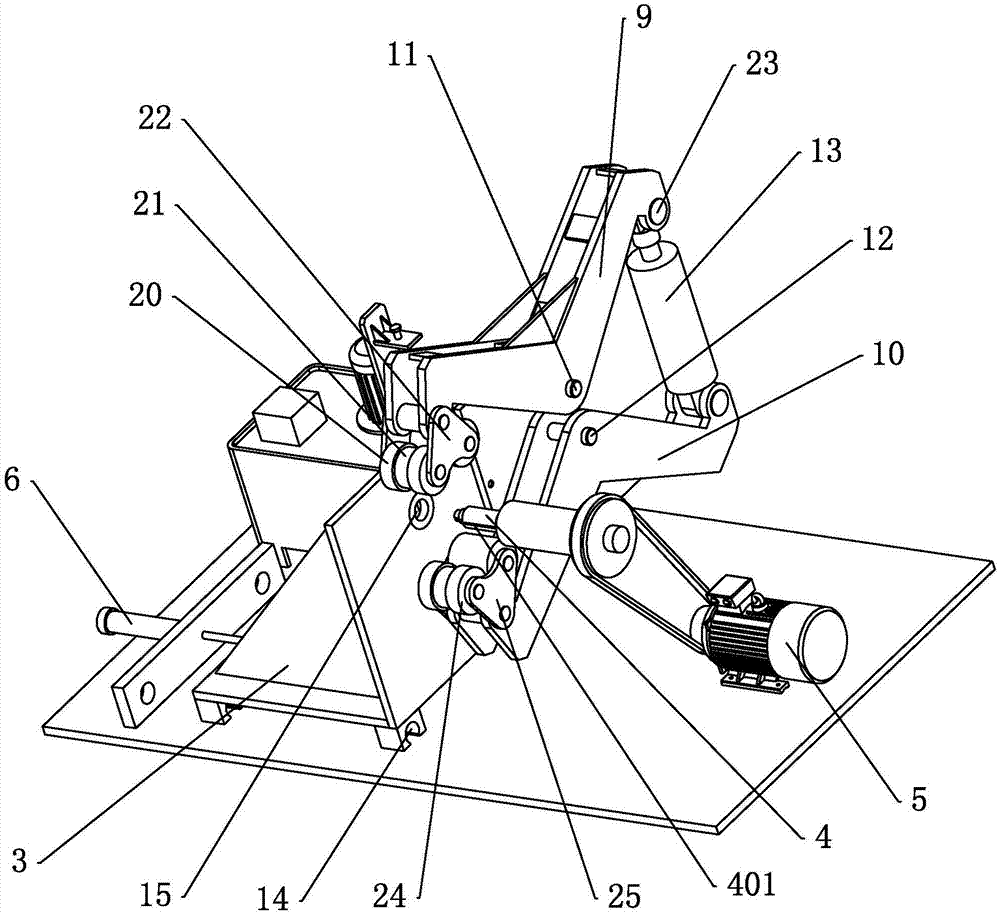
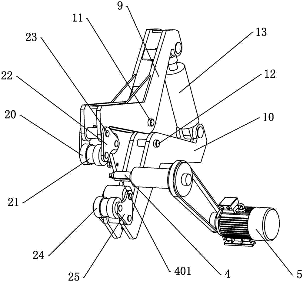
[0034] Embodiment 1: a kind of coil spring machine, as figure 1 with figure 2 As shown, it includes a horizontal base 1, the base 1 is provided with a first side frame 2 perpendicular to the surface of the base 1, and the first side frame 2 is provided with a coil spring shaft 4 and a driving motor for driving the coil spring shaft 4 to rotate 5. The coil spring shaft 4 is rotationally connected with the surface of the first side frame 2, the axis of the coil spring shaft 4 is perpendicular to one side surface of the first side frame 2, and the outer peripheral surface of the coil spring shaft 4 is provided with a spring plate snap into the fixed slot 401 together with the gasket, and the slot 401 extends upward along the axis of the coil spring shaft 4;

[0035] The surface of the base 1 is slidingly connected with the second side frame 3, the first side frame 2 is opposite to the second side frame 3 left and right, the base 1 is provided with a driving part 6, and the driv...

Embodiment 2

[0049] Embodiment 2: A kind of spring rolling process, use embodiment 1 to carry out the coil spring production, the steps of this process are as follows: one end of the strip-shaped spring piece and one end of the gasket are snapped onto the coil spring shaft 4 together, and the length of the gasket is , the width is the same as the length and width of the spring sheet, the gasket is attached to the outer surface of the spring sheet, and the coil spring shaft 4 rotates to drive the spring sheet and the gasket to be wound together; after the coiling of the spring is completed, the gasket is manually Remove from spring.


PUM


Abstract

The invention discloses a spring coiling machine and a spring coiling process. The spring coiling machine is characterized in that an upper pressing arm is V-shaped, and of which the middle is rotatably connected with a first rotating shaft; a lower pressing arm is inverted V-shaped, and of which the middle is rotatably connected with a second rotating shaft; upper pressing rolls used for downwards pressing a spring on a spring coiling shaft are arranged at the end, close to the spring coiling shaft, of the upper pressing arm; lower pressing rolls used for upwards pressing the spring on the spring coiling shaft are arranged at the end, close to the spring coiling shaft, of the lower pressing arm; the end, away from the spring coiling shaft, of the upper pressing arm is movably connected with the piston rod of an air cylinder; and the end, away from the spring coiling shaft, of the lower pressing arm is movably connected with the bottom of the air cylinder body. The spring coiling machine and the spring coiling process have the benefits as follows: the pressure is applied on the spring through the same air cylinder, so that the spring is under a uniform and equal pressure during the coiling process, the problem that the surface of the spring is under a non-uniform pressure is avoided, the spring after coiling is rounder and in accordance with the spring coiling requirement.

Description

technical field [0001] The invention relates to the field of spring rolling technology, in particular to a spring rolling machine and a spring rolling technology. Background technique [0002] Spring is a commonly used component in the industry. It is used in various products ranging from aircraft and warships to mobile phones and cameras. Most of the existing springs are produced by coiling spring machines. [0003] At present, in the prior art, in a Chinese patent document with the authorized announcement number CN203091616U, a coil spring device is recorded. At the clamping hole, the coil spring shaft rotates to roll the spring sheet. A spring retraction cylinder is arranged on the support plate. A spring retraction push rod is arranged at the lower end of the spring retraction cylinder. The upper guide wheel oil cylinder is arranged on the wheel frame, and the upper guide wheel is arranged at the front end of the upper guide wheel oil cylinder. [0004] However, the up...

Claims


Application Information

Patent Timeline
Patent Type & Authority Applications(China)
IPC IPC(8): B21D11/10
CPCB21D11/10
Inventor 金晨沈小木
Owner 浙江裕荣弹簧有限公司
Learn More