Centering and rotating device for assembly of high-pressure compressor of aero-engine

An aero-engine and rotating device technology, which is applied to workpiece clamping devices, aircraft parts, transportation and packaging, etc., can solve the problems of affecting the inspection quality, inflexible rotor rotation, and unadjustable centering structure, and achieves convenient assembly and disassembly. Good detection conditions, flexible rotation effect

Pending Publication Date: 2017-10-20
CHINA HANGFA GUIZHOU LIYANG AVIATION POWER CO LTD
View PDF8 Cites 4 Cited by
  • Summary
  • Abstract
  • Description
  • Claims
  • Application Information

AI Technical Summary

Problems solved by technology

Due to the non-adjustable centering structure of the existing assembly fixture, the gap m between the rotor and the compressor shell cannot be guaranteed, resulting in inflexible rotation of the rotor and affecting the subsequent inspection quality

Method used


Image

  • Centering and rotating device for assembly of high-pressure compressor of aero-engine
  • Centering and rotating device for assembly of high-pressure compressor of aero-engine
  • Centering and rotating device for assembly of high-pressure compressor of aero-engine

Examples


Embodiment Construction

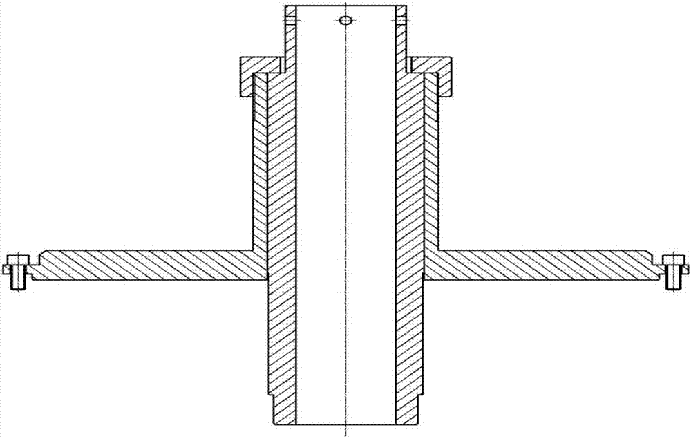
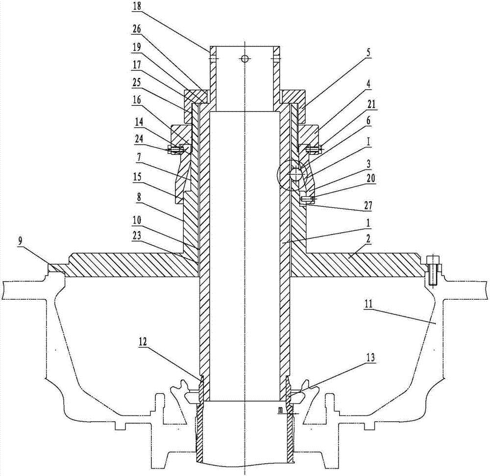
[0016] Below the present invention is described in further detail, see figure 2 and image 3 , the size of the reference hole of the compressor housing 11 is ф420mm, and the size of the center hole of the rotor 13 is ф100mm. The aeroengine high-pressure compressor of the present invention is assembled with a centering and rotating device, which includes: a mandrel 1, a base mandrel 2. Adjusting sleeve 3, adjusting nut 4, compression nut 5, 3 steel balls 6, positioning pin 20, 4 set screws 21 and screws.

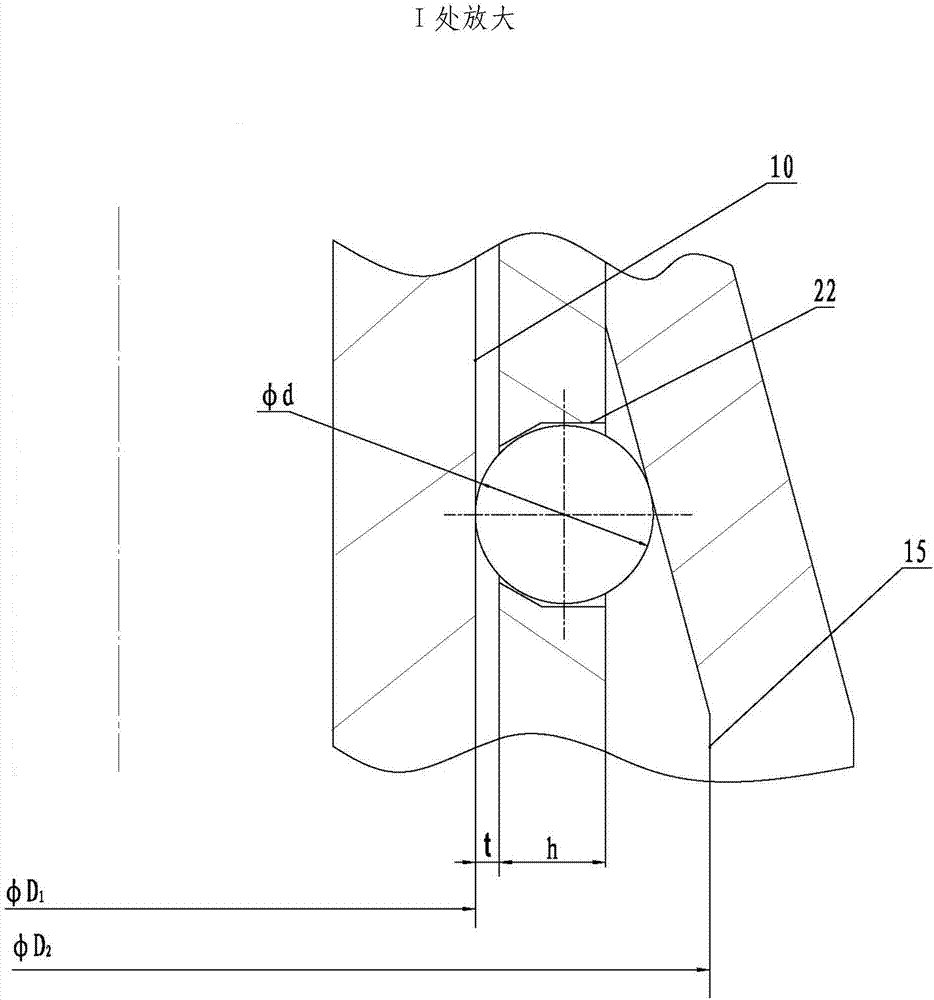
[0017] The mandrel 1 is composed of three concentric cylinders with different diameters, and the lowest cylindrical section I12 and the center hole of the rotor 13 ensure the interference fit of H7 / p6. Connected with the cylindrical section I12 is the centering cylindrical section 10, the diameter of the centering cylindrical section 10 is D 1 =110mm, the diameter difference between the centering cylinder section 10 and the cylinder section I12 forms a step surface; the ot...


PUM


Abstract

The invention belongs to a technology of assembling an aero-engine, and relates to a centering and rotating device for assembly of a high-pressure compressor of an engine. The centering and rotating device is characterized by comprising a mandrel (1), a base mandrel (2), an adjusting sleeve (3), an adjusting nut (4), a pressing nut (5), n' steel balls (6), a positioning pin (20), n set screws (21) and screws. During assembling of the high-pressure compressor of the aero-engine, a gap m between a rotor (13) and a compressor shell (11) can meet a design requirement, the rotor (13) can flexibly rotate in the compressor shell (11), the requirement on follow-up circumferential detection of the rotor (13) and blades is met, and meanwhile, a clamp is convenient to assemble and disassemble when used.

Description

technical field [0001] The invention belongs to the assembly technology of aero-engines, and relates to a centering and rotating device for assembling high-pressure compressors of engines. Background technique [0002] When the high-pressure compressor of the engine is assembled, the compressor shell and the rotor must be fixed to each other while ensuring concentricity, so that the rotor can rotate freely, so that the circumferential detection of the rotor and blades can be performed. The existing assembly fixture cannot guarantee the gap m between the rotor and the compressor shell due to the non-adjustable centering structure, resulting in inflexible rotation of the rotor and affecting the subsequent inspection quality. Contents of the invention [0003] The purpose of the present invention is to: propose a kind of assembly centering device of aero-engine high-pressure compressor, utilize this device when aero-engine high-pressure compressor is assembled, can guarantee ...

Claims


Application Information

Patent Timeline
Patent Type & Authority Applications(China)
IPC IPC(8): B23P19/00B25B11/02
CPCB23P19/00B25B11/02B23P2700/01
Inventor 龙静李平罗大臣姜勃
Owner CHINA HANGFA GUIZHOU LIYANG AVIATION POWER CO LTD
Why Eureka
Try Eureka