Device for mounting interference fit pin shafts in drawing manner and method for mounting interference fit pin shafts

A technology of interference fit and pin shaft, which is applied in the direction of hand-held tools and manufacturing tools, can solve the problems of low installation accuracy, difficulty in installation, and low installation efficiency, so as to reduce auxiliary requirements and difficulties, and achieve high installation efficiency. The smooth effect of the installation process

Inactive Publication Date: 2017-10-20
LIUZHOU OVM MASCH CO LTD
View PDF6 Cites 6 Cited by
  • Summary
  • Abstract
  • Description
  • Claims
  • Application Information

AI Technical Summary

Problems solved by technology

The manual hammering method is relatively rough in operation, has a large impact, and the hammering will damage the surface quality of the parts; the press-in method improves the shortcomings of the manual hammering method, but there is no traction guide mechanism during the pressing process, and the installation accuracy is not high. The centering assistance requirements for workpiece holes and holes are relatively high; the hot-filling and cold-filling methods have high requirements for ambient temperature and service conditions, which brings inconvenience to the installation
In order to overcome the shortcomings of the above methods, there is an installation method described in the patent "ZL 200820158285.1 Installation Tool for Interference Fit", but this method uses a thread structure for force transmission installation, which has low installation efficiency and laborious installation, especially When the interference is large, it will be difficult to install

Method used


Image

  • Device for mounting interference fit pin shafts in drawing manner and method for mounting interference fit pin shafts
  • Device for mounting interference fit pin shafts in drawing manner and method for mounting interference fit pin shafts
  • Device for mounting interference fit pin shafts in drawing manner and method for mounting interference fit pin shafts

Examples


Embodiment 1

[0075] A device A for installing interference-fit pin shafts in a pull-out manner and a method for installing interference-fit pin shafts:

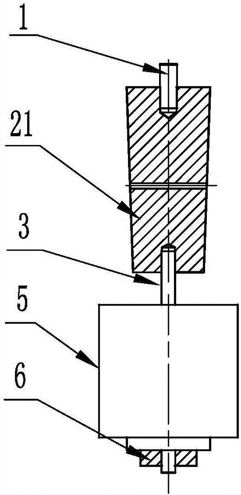
[0076] like figure 1 As shown, the basic structure of the device A of the pull-type installation interference fit pin includes a draw bar, a tension rod, a jack 5 and a nut 6, and it also includes a screw 1;

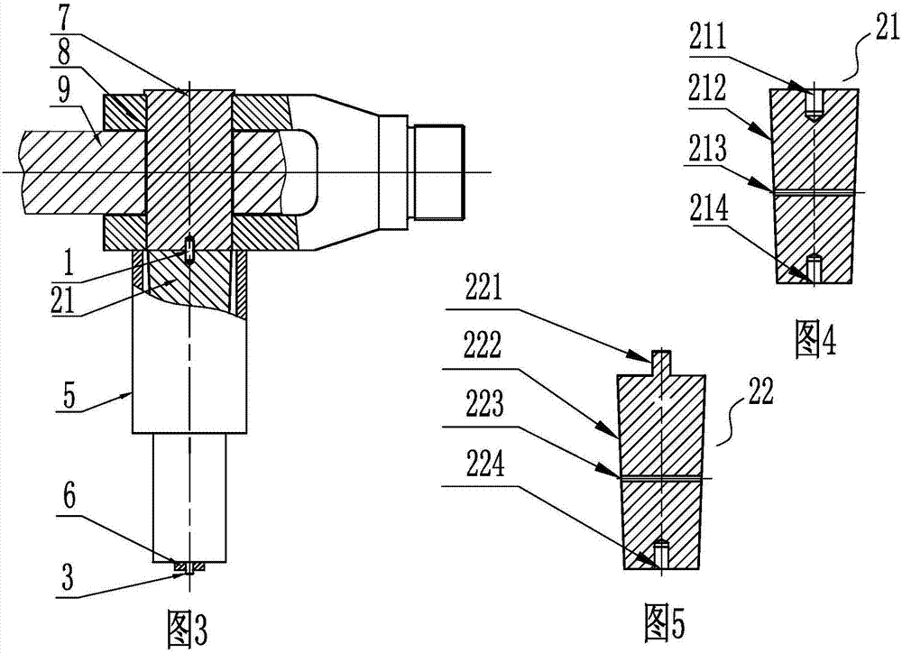
[0077] Described drawing rod is the drawing rod I21 (referring to Figure 4 ), under working condition, one end of the screw 1 is connected with the threaded hole 211 in the center of the large end face of the drawbar I21, and the other end of the screw 1 is connected with the pin 7 through the threaded hole on the pin 7; the thread in the center of the small end of the drawbar The hole is connected with the threaded end 31 of the tension rod II3b or tension rod I3a; the tension rod passes through the installation hole of the fork lug and the pin shaft, so that the tapered surface of the draw rod snaps into the installation hole of...

Embodiment 2

[0082] A device B for pulling and installing interference fit pins:

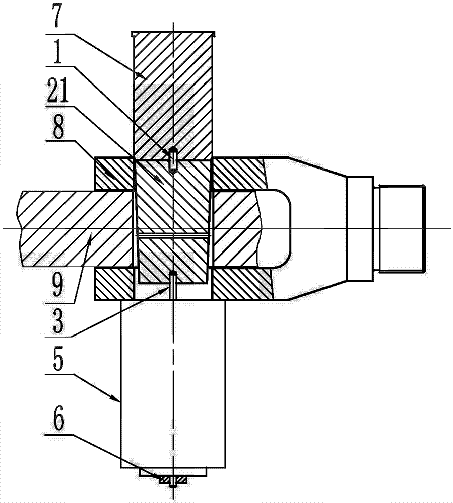
[0083] like Figure 7 As shown, its basic structure includes draw bar, tension bar, jack 5 and nut 6;

[0084] The drawbar is a drawbar II22 with a raised connecting thread 221 in the center of its large end face (see Figure 5 ), in the working state, the connecting thread 221 protruding from the center of the large end face of the draw rod II is connected with the pin shaft 7 through the threaded hole on the pin shaft 7; The threaded end 31 is connected; the tension rod passes through the installation hole of the fork lug and the pin shaft, so that the tapered surface of the draw rod snaps into the installation hole of the fork lug; the tension rod passes through the jack 5, and passes through the tension rod II3b or tension rod I3a Pull thread end 33 is connected with nut, and the bottom end of jack 5 is pressed on the fork lug (referring to Figure 8 ).

[0085] The basic steps of the method of using...

Embodiment 3

[0088] A device C for pulling and installing interference fit pins:

[0089] like Figure 10 As shown, the basic structure of the device C of the pull-type installation interference fit pin is the same as that of the first embodiment, including a screw 1, a draw bar, a tension bar 3, a jack 5 and a nut 6, and the draw bar is its large end surface Drawbar I21 with threaded hole 211 in the center (see Figure 4 ), differs from Embodiment 1 in that:

[0090] It also includes a support foot 4. Under the working condition, the tension rod 3 passes through the support foot 4 and the jack 5, and is connected with the nut through the tension thread end 33 of the tension rod II 3b or the tension rod I 3a, so that the bottom end of the support foot 4 is pressed on the On the fork lug, the bottom end of the jack 5 is pressed on the support foot 4 (see Figure 11 ).

[0091] The basic steps of the method of using the device C for installing interference fit pin shafts in a pull-out ma...


PUM


Abstract

The invention discloses a device for mounting interference fit pin shafts in a drawing manner. The device comprises a traction rod, a tension rod, a jack and a nut; the traction rod is provided with a conical surface; the tension rod comprises a tension rod I or a tension rod II; the tension rod II is a screw rod with threads on full length; the tension rod I is a slender round rod; in a working state, a large end of the traction rod is connected with a pin shaft; a thread hole in the center of a small end of the traction rod is connected with a connecting thread end of the tension rod II or the tension rod I; the tension rod penetrates through mounting holes of a fork lug and the pin shaft, so that the conical surface of the traction rod is clamped into the mounting hole of the fork lug; the tension rod penetrates through the jack, and is connected with the nut through a tension thread end of the tension rod II or the tension rod I; and the bottom end of the jack is pressed on the fork lug. The device stably mounts the interference fit pin shafts at low speed through the traction rod, the tension rod and the jack, is simple and reliable in structure, high in mounting precision and simple in mounting method, and in particular, is suitable for installation of the interference fit pin shafts aerially assembled on the engineering field.

Description

technical field [0001] The invention relates to an auxiliary device for building construction, in particular to a pull-type device for installing an interference fit pin shaft and a method for installing the interference fit pin shaft. Background technique [0002] At present, the methods for installing interference fit pins mainly include: manual hammering method, press-in method, hot-fitting method and cold-fitting method. The manual hammering method is relatively rough in operation, has a large impact, and the hammering will damage the surface quality of the parts; the press-in method improves the shortcomings of the manual hammering method, but there is no traction guide mechanism during the pressing process, and the installation accuracy is not high. The centering aid requirements for workpiece holes and holes are relatively high; the hot-loading and cold-packing methods have high requirements for ambient temperature and service conditions, which brings inconvenience to...

Claims


Application Information

Patent Timeline
Patent Type & Authority Applications(China)
IPC IPC(8): B25B27/02
CPCB25B27/02
Inventor 雷欢庞锐剑邹易清苏韩韦耀淋范玲覃巍巍荣林蒋立军覃磊宁绍锋罗迪
Owner LIUZHOU OVM MASCH CO LTD
Why Eureka
Try Eureka