adaptive impact bed

An adaptive and buffer bed technology, applied in the field of conveying machinery, can solve the problems of smashing the conveyor belt and buffer rollers, increasing the possibility of tearing the conveyor belt, and increasing the running resistance of the whole machine, so as to improve the service life. , The effect of uniform force and reduced maintenance cost

Active Publication Date: 2018-12-04
安徽宏昌机电装备制造有限公司
View PDF6 Cites 0 Cited by
  • Summary
  • Abstract
  • Description
  • Claims
  • Application Information

AI Technical Summary

Problems solved by technology

[0002] In the prior art, the feeding point of the belt conveyor is usually supported by ordinary rollers or buffer rollers. This structure often results in a suspended section of the conveyor belt, resulting in a large impact tension, and at the same time makes the conveying The possibility of belt tearing increases, and when the free fall of large pieces of material is large, it is easy to damage the conveyor belt and buffer idler, and when the idler is damaged and the spilled material accumulates, it is easy to cause the running resistance of the whole machine to increase. When affected by the uneven wear of the buffer roller rubber ring, it is easy to cause the conveyor belt to deviate, and this type of buffering method has a short service life

Method used


Image

  • adaptive impact bed
  • adaptive impact bed
  • adaptive impact bed

Examples


Embodiment Construction

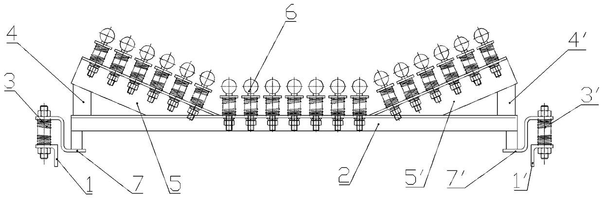
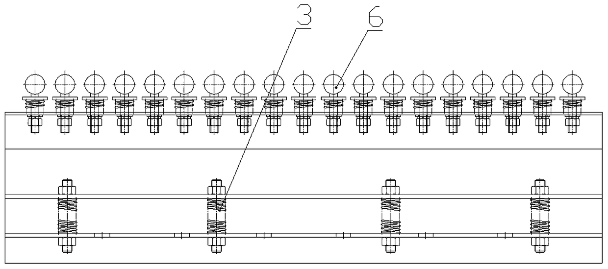
[0012] Such as figure 1 , figure 2 , image 3 It can be seen that the adaptive impact bed of this embodiment includes a bed base 2, and the two ends of the bed base 2 are respectively provided with left and right connecting plates 5, 5' via left and right support plates 4, 4', The left and right connecting plates 5, 5' cooperate with the bed base 2 to form a U-shaped groove, and the upper end surface of the U-shaped groove is uniformly provided with a plurality of through holes, and a buffer block assembly 6 is movably arranged on the through holes .

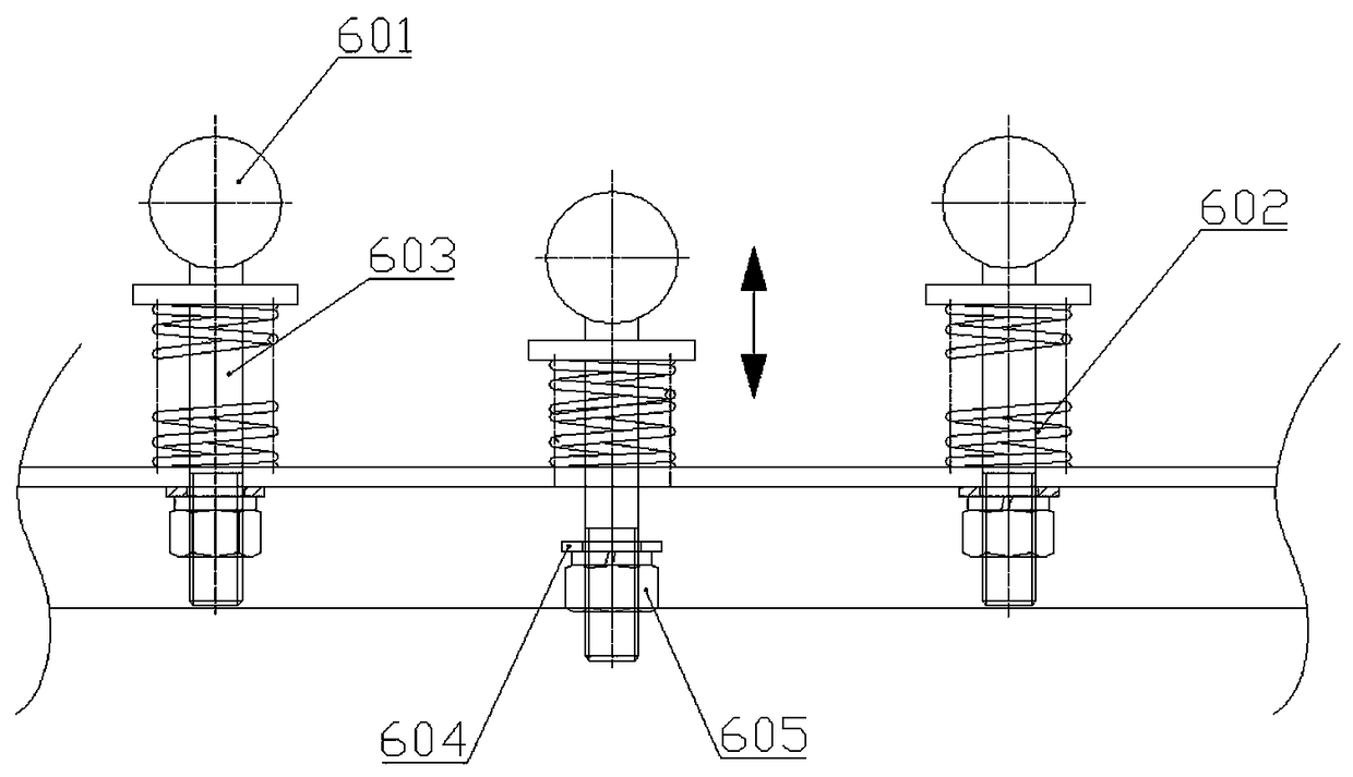
[0013] The buffer block assembly 6 includes a spherical buffer block 601, a compression spring 602 and a support column 603, the spherical buffer block 601 is connected to the support column 603, and the compression spring 602 is sleeved on the support column 603 , the end of the support column 603 passes through the through hole on the upper end surface of the U-shaped groove and is connected to the limiting device, and the...


PUM


Abstract

The invention provides an adaptive buffer bed. The adaptive buffer bed is good in buffer performance, safe, reliable, simple in structure, convenient to mount and use, low in failure rate and easy to maintain. The adaptive buffer bed comprises a bed body base, a U-shaped groove is formed in the bed body base, and the buffer bed is characterized in that multiple through holes are evenly distributed in the upper end face of the U-shaped groove, a buffer block assembly is movably arranged on each through hole, each buffer block assembly comprises a spherical buffer block, a compression spring and a supporting column, the spherical buffer blocks are connected with the supporting columns, the supporting columns are sleeved with the compression springs, the tail ends of the supporting columns penetrate the through holes in the upper end face of the U-shaped groove and then are connected with limiting devices, and the supporting columns are in clearance fit with the through holes; and the spherical buffer blocks and the supporting columns are in threaded connection.

Description

technical field [0001] The invention relates to conveying machinery, in particular to a buffer bed for a belt conveyor. Background technique [0002] In the prior art, the feeding point of the belt conveyor is usually supported by ordinary rollers or buffer rollers. This structure often results in a suspended section of the conveyor belt, resulting in a large impact tension, and at the same time makes the conveying The possibility of belt tearing increases, and when the free fall of large pieces of material is large, it is easy to damage the conveyor belt and buffer idler, and when the idler is damaged and the spilled material accumulates, it is easy to cause the running resistance of the whole machine to increase. When affected by the uneven wear of the buffer roller rubber ring, it is easy to cause the conveyor belt to deviate, and this type of buffering method has a short service life. Contents of the invention [0003] The technical problem to be solved by the present...

Claims


Application Information

Patent Timeline
Patent Type & Authority Patents(China)
IPC IPC(8): B65G15/60
CPCB65G15/60
Inventor 储凯煜肖永东江波
Owner 安徽宏昌机电装备制造有限公司
Why Eureka
Try Eureka