
Luminous road plate

A board and road technology, which is applied in the field of luminous road boards, can solve the problems of lack of luminous function and single characteristics of cement boards, and achieve the effects of stable connection, stable structure, and convenient up and down

Inactive Publication Date: 2017-10-20
合肥慧林建材有限公司
View PDF6 Cites 2 Cited by
  • Summary
  • Abstract
  • Description
  • Claims
  • Application Information

AI Technical Summary

Problems solved by technology

[0003] At present, most of the materials used as road boards are cement boards, but the characteristics of cement boards are relatively single, and they do not have the function of luminescence. They cannot meet the requirements in some specific roads, such as the boards of garden roads, so a road board that can emit light is needed. meet the above requirements

Method used


Image

  • Luminous road plate
  • Luminous road plate
  • Luminous road plate

Examples


Embodiment 1

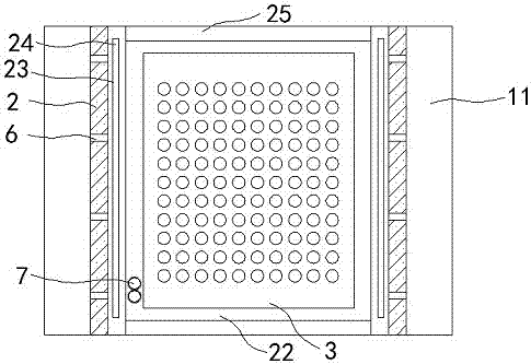
[0028] Such as Figure 1~3 Shown is a luminous road board in this embodiment, including a cement base 1, and a raised strip 11 is provided on the left and right sides of the cement base 1, and an installation cavity 111 with an upward opening is formed in the middle of the two raised strips 11. A metal base 2 is seamlessly installed in the installation cavity 111 and the metal base 2 protrudes from the installation cavity 111. There is an accommodation cavity 22 in the middle of the metal base 2. The PCB board 3 is installed in the accommodation cavity 22, and the top surface of the PCB board 3 There are a plurality of LED patch lamps 4; the metal seat 2 is provided with two notches 23 on the left and right sides of the opening of the accommodating cavity 22, and the left and right ends of a toughened glass plate 5 are correspondingly snapped on the two notches 23 and The top surface of tempered glass plate 5 is flush with the top surface of metal seat 2 .

[0029] The metal ...

Embodiment 2

[0045] Such as Figure 2~4Shown is a luminous road board in this embodiment, including a cement base 1, and a raised strip 11 is provided on the left and right sides of the cement base 1, and an installation cavity 111 with an upward opening is formed in the middle of the two raised strips 11. A metal base 2 is seamlessly installed in the installation cavity 111 and the metal base 2 protrudes from the installation cavity 111. A storage cavity 22 is provided in the middle of the metal base 2, and a plurality of lifting devices are provided on the bottom surface of the storage cavity 22. 8. A horizontal PCB board 3 is installed on the top of a plurality of lifting devices 8, and a plurality of LED patch lamps 4 are arranged on the top surface of the PCB board 3; Notches 23 , the left and right ends of a tempered glass plate 5 are correspondingly clamped on the two notches 23 and the top surface of the tempered glass plate 5 is flush with the top surface of the metal seat 2 .

...


PUM


Abstract

The invention discloses a luminous road plate, and relates to the technical field of road plates. The luminous road plate comprise a cement base, raised lines are arranged on the left side and the right side of the cement base correspondingly, and a mounting cavity with an upward opening is formed between the two raised lines; a metal seat is seamlessly mounted in the mounting cavity, and the metal seat raises out of the mounting cavity; a containing cavity is formed in the middle of the metal seat, a PCB plate is mounted in the containing cavity, and a plurality of LED surface-mounted lamps are arranged on the top face of the PCB plate; and two gaps are correspondingly formed in the left side and the right side of an opening of the containing cavity of the metal seat, the left end and the right end of a tempered glass plate are clamped in the two gaps correspondingly, and the top face of the tempered glass plate is level with the top face of the metal seat. The luminous road plate is stable and secure in structure, achieves the luminous function of the road plate, and has good waterproof function.

Description

technical field [0001] The invention belongs to the technical field of road boards, in particular to a luminous road board. Background technique [0002] Panels are usually manufactured as flat rectangular building material panels of standard sizes for use as wall, ceiling or floor elements. It also refers to forged, rolled or cast metal plates. Plates are usually divided into thin plates, medium plates, thick plates, extra-thick plates, and are usually made into flat rectangular building material plates of standard size. The plate products are flat in shape, large in width-to-thickness ratio, and have a large surface area per unit volume. This shape feature brings The characteristics of its use: (1) It has a large surface area, so it has a strong ability to contain and cover, and it is widely used in chemical industry, containers, construction, metal products, metal structures, etc.; (2) It can be cut, bent, stamped, and welded arbitrarily , made into various product comp...

Claims


Application Information

Patent Timeline
IPC IPC(8): E01C5/00E01F9/50
CPCE01C5/001E01F9/50
Inventor 刘伍
Owner 合肥慧林建材有限公司
Learn More