
Shore-side filter type floating flock collecting device

A collection device and filtering technology, which is applied in the field of shore filter floating floc collection device, can solve problems affecting water quality, affecting landscape, rot, etc., and achieve the effect of maintaining water quality, keeping water surface clean and low maintenance cost

Active Publication Date: 2017-10-20
SHANDONG JIANZHU UNIV
View PDF7 Cites 4 Cited by
  • Summary
  • Abstract
  • Description
  • Claims
  • Application Information

AI Technical Summary

Problems solved by technology

[0002] Every April and May, catkins and catkins fly all over the sky, and many fly into rivers and lakes to form floating catkins on the water surface. Because the water flow in the river is fast and the water cycle is obvious, there will be no large-scale accumulation of catkins, but the water flow in the lake is relatively gentle and the water cycle is not obvious. Therefore, it is particularly easy to form floating floc accumulation. The breeze blows across the water surface, and the floating flocs float with the wind to the shore (especially the concave shore) and accumulate in large quantities, especially in scenic spots, which seriously affect the landscape, and accumulation on the water surface for a long time will cause rot and affect water quality.
Although there are some land-based catkin prevention methods on the market, such as: catkin-proof nets, vacuum cleaner-type catkin collection devices, and biological catkin prevention, etc., it is inevitable that catkins will float into the lake and accumulate. Large garbage can be cleaned manually, and small floating catkins If the flocs are only cleaned manually, it will not only waste manpower and material resources, but also the efficiency is extremely low, but there is no effective device for cleaning floating flocs on the lake surface

Method used


Image

  • Shore-side filter type floating flock collecting device
  • Shore-side filter type floating flock collecting device
  • Shore-side filter type floating flock collecting device

Examples


Embodiment Construction

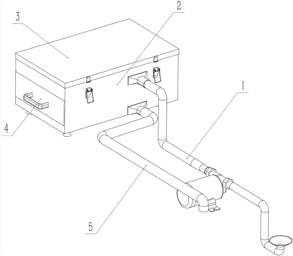
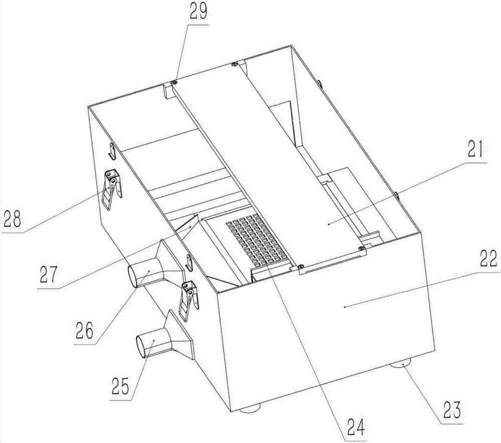
[0017] A shore filter floating flocculation collection device is composed of a water inlet part 1, a device main body 2, an upper cover 3, a drawer type filter bin 4, and a drainage pipe 5, and is characterized in that the upper cover is installed on the device main body 2 3. A drawer-type filter bin 4 is installed on one side, and a water inlet part 1 and a drain pipe 5 are installed on the other side.

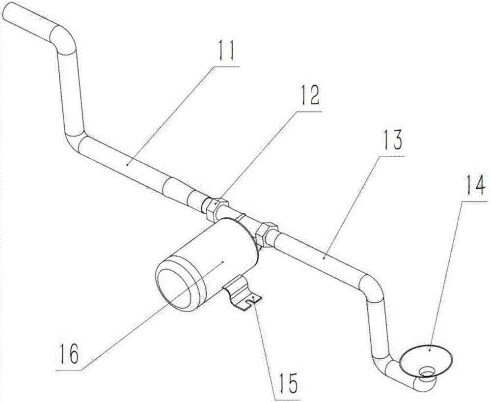
[0018] The water inlet part 1 is composed of an upper water inlet pipe 11, a compression nut 12, a lower water inlet pipe 13, a trumpet-shaped water inlet 14, a water pump support 15, and a water pump 16. It is characterized in that: the upper water inlet pipe 11 passes through the compression nut 12 Installed in the water outlet of water pump 16, lower inlet pipe 13 one end is installed in water pump 16 water inlets by compression nut 12, and its other end is equipped with trumpet-shaped water inlet 14, and water pump 16 bottoms are provided with water pump support 15.

[00...


PUM


Abstract

The invention discloses a shore-side filter type floating flock collecting device, and belongs to the field of environmental cleaning equipment. The shore-side filter type floating flock collecting device consists of a water inlet part, a device main body, an upper cover, a drawer type filter bin and a water draining tube, wherein the upper cover is mounted on the device main body; the drawer type filter bin is mounted on the side surface of the upper cover; and the water inlet part and the water draining tube are mounted on the other side surface of the upper cover. The shore-side filter type floating flock collecting device is small in size, is low in manufacturing cost, is simple and convenient to maintain, can realize 24-hour automatic continuous collecting work of small floating substances such as lake floating flock, is good in effect, is convenient to popularize and apply, and can save a great deal of human and material resources.

Description

technical field [0001] The invention relates to a bank filter type floating floc collection device, in particular to a device for collecting floating flocs formed by flying flocs floating into water on the shore, belonging to the field of environmental cleaning equipment. Background technique [0002] Every April and May, catkins and catkins fly all over the sky, and many fly into rivers and lakes to form floating catkins on the water surface. Because the water flow in the river is fast and the water cycle is obvious, there will be no large-scale accumulation of catkins, but the water flow in the lake is relatively gentle and the water cycle is not obvious. Therefore, it is particularly easy to form floating floc accumulation. The breeze blows across the water surface, and the floating flocs float with the wind to the shore (especially the concave shore) and accumulate in large quantities, especially in scenic spots, which seriously affect the landscape, and accumulation on t...

Claims


Application Information

Patent Timeline
IPC IPC(8): E02B15/10
CPCE02B15/10Y02A20/402
Inventor 任秀华田亚强徐跃学李建勇张超李明辉
Owner SHANDONG JIANZHU UNIV
Learn More