Multi-energy hybrid power hydraulic pumping unit

A technology of hybrid power and pumping unit, applied in mechanical structure design, hydraulic pumping unit field, to achieve remarkable effect of energy saving

Inactive Publication Date: 2017-10-20
李振河
View PDF5 Cites 2 Cited by
  • Summary
  • Abstract
  • Description
  • Claims
  • Application Information

AI Technical Summary

Problems solved by technology

[0003] In order to solve the above-mentioned shortcomings of the traditional beam pumping unit and the current hydraulic pumping unit, the present invention adopts a mechanical structure design in which the double wells are mutually balanced, or a single well plus counterweight can be used in the area where the double wells are not suitable for use. Balanced structural design, while the drive system adopts the hydraulic constant pressure network hydrostatic secondary regulation technology without throttling loss and the new energy technology of small-scale wind-solar hybrid power generation. During the acceleration stage, the pumping unit is driven by hydraulic pressure and can be adjusted in real time to adapt to In the low power condition of the constant speed stage, it is directly driven by the power provided by the wind and solar hybrid power generation system, so as to achieve the purpose of energy saving and high efficiency

Method used


Image

  • Multi-energy hybrid power hydraulic pumping unit
  • Multi-energy hybrid power hydraulic pumping unit

Examples


Embodiment 1

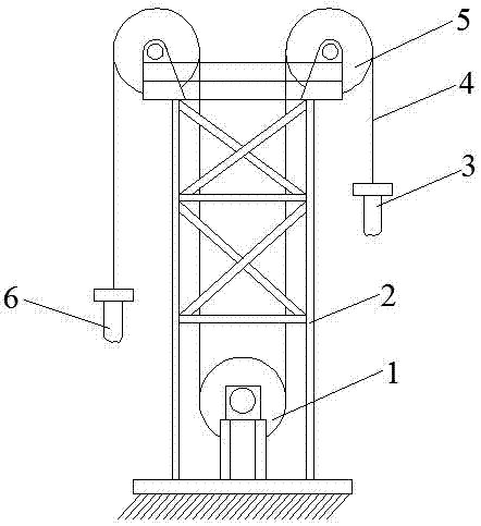
[0011] Such as figure 1 As shown, the mechanical structural unit of the new energy-saving hydraulic pumping unit is mainly composed of a driving drum, a frame, a sucker rod 1 and a sucker rod 2, a steel wire rope, two sky wheels and the like. The two sucker rods are connected by wire ropes after passing through the crown wheel, and are balanced and symmetrically arranged on both sides of the driving drum, and the wire ropes on both sides of the driving drum are wound in opposite directions, so that when the sucker rod on the side of the driving drum rises to pump oil At the same time, the sucker rods on the other side are lowered synchronously, forming double wells to operate alternately to pump oil, and achieve continuous oil pumping. In addition, for oil production areas where it is not suitable to install two oil wells at a relatively short distance, the sucker rod on the side of the drive drum can be changed to a balance counterweight. Well pumping oil.

Embodiment 2

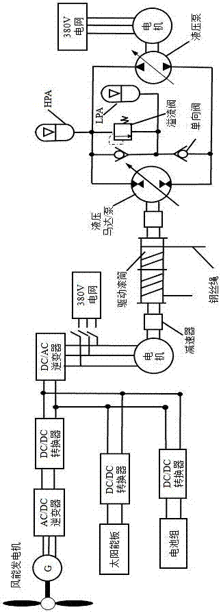
[0013] Such as figure 2 As shown, the drive system of the new energy-saving hydraulic pumping unit is composed of a hydraulic hydrostatic transmission system and a small wind-solar hybrid power generation system. Among them, the hydraulic hydrostatic transmission system is mainly composed of motor, variable hydraulic pump, check valve, overflow valve, high pressure accumulator (HPA), low pressure accumulator (LPA), secondary component hydraulic motor / pump and hydraulic pipeline . The small-scale wind-solar hybrid power generation system is mainly composed of wind power generators, AC / DC inverters, DC / DC converters, solar panel arrays, battery packs, etc. Its main working principle is as follows:

[0014] When the sucker rod is in the acceleration stage, the energy is provided by the hydraulic system at this time, and the secondary element works according to the motor condition and adjusts the displacement in real time according to the load to meet the load demand; The powe...

Embodiment 3

[0016] Such as figure 2 As shown, the wind power generation system can also work in the grid-connected mode. At this time, the switch is closed, and the electric energy generated by the wind power generation system is used to drive the motor and drive the sucker rod to run at a constant speed. If the power generated by the wind power generation system is excessive , will be directly incorporated into the grid, and when the generated electric energy is insufficient, it can directly absorb energy from the grid to drive the motor to run normally.


PUM


Abstract

The invention discloses a multi-energy hybrid power hydraulic pumping unit. The pumping unit is composed of a mechanical portion and a hybrid power driving portion. The mechanical structure of the pumping unit is arranged in a symmetric balanced mode, in other words, two pumping units or a single pumping unit and a balance weight are symmetrically arranged on the two sides of a driving roller after passing through a crown sheave, and a steel wire rope on the driving roller is wound in the opposite direction, so that when a pumping rod on one side ascends, a pumping rod on the other side or the weight synchronously descend; the driving portion of the pumping unit is composed of multi-energy hybrid power, a hydraulic hydrostatic transmission system is adopted for driving the roller during acceleration, a wind and photovoltaic complementary power generation system is adopted for direct driving in the constant speed stage, the system efficiency is improved, clean and pollution-free renewable energy sources are utilized, and the energy-saving effect is remarkable.

Description

technical field [0001] The invention is a hydraulic pumping unit that adopts new energy technology and is driven by hybrid power. It is applied in the field of oil production equipment engineering, and its technology involves the fields of mechanical structure design, hydraulic secondary adjustment, new energy and the like. Background technique [0002] According to research, the electric energy consumed by oil production equipment accounts for more than 20% of the total power consumption of oil production. Facing the increasingly severe energy crisis, it is very important to improve or develop new oil production equipment to achieve energy saving. The traditional beam pumping unit not only has complex mechanical structure, high manufacturing cost, but also low work efficiency, generally only 12-23% in China, and only about 30% of this type of pumping unit abroad; on the contrary , the hydraulic pumping unit has been developed rapidly due to its light weight, small size, ste...

Claims


Application Information

Patent Timeline
Patent Type & Authority Applications(China)
IPC IPC(8): E21B43/00F04B47/14
CPCE21B43/129F04B47/14
Inventor 不公告发明人
Owner 李振河
Why Eureka
Try Eureka