

A passive magnetic spring
A technology of magnetic springs and permanent magnets, applied in the direction of magnetic springs, springs, springs/shock absorbers, etc., can solve the problems of complex manufacturing process and high cost, and achieve the effects of compact structure, high thrust density and high reliability
- Summary
- Abstract
- Description
- Claims
- Application Information
AI Technical Summary
Problems solved by technology
Method used
Image

Examples
Embodiment 1
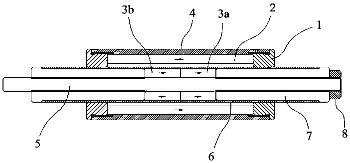
[0023] like figure 1 In the shown embodiment, a passive magnetic spring includes a stator and a mover 5, the stator includes a casing 4 and two stator shaft ends 1, the stator shaft ends are respectively located at the ends of the casing, and the ends of the casing are connected to the stator shaft ends Thread fit. The stator is provided with a stator permanent magnet 2, the magnetic pole direction of the stator permanent magnet is parallel to the stator axial direction, the stator permanent magnet is located between the two stator shaft ends, and the stator shaft end clamps and positions the stator permanent magnet.
[0024] The mover is provided with two mover shaft ends 7 and two mover permanent magnets, the mover is provided with an external thread, and the mover shaft end is provided with an internal thread matched with the external thread. The two mover permanent magnets are the first mover permanent magnet 3a and the second mover permanent magnet 3b, the mover permanen...
Embodiment 2
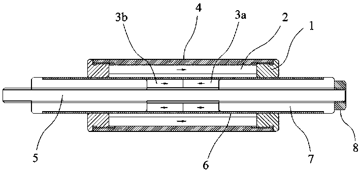
[0027] like image 3 In the shown embodiment, a passive magnetic spring includes a stator and a mover 5, the stator includes a casing 4 and two stator shaft ends 1, the stator shaft ends are respectively located at the ends of the casing, and the ends of the casing are connected to the stator shaft ends Thread fit. The stator is provided with a stator permanent magnet 2, the magnetic pole direction of the stator permanent magnet is parallel to the stator axial direction, the stator permanent magnet is located between the two stator shaft ends, and the stator shaft end clamps and positions the stator permanent magnet.
[0028] The mover is provided with two mover shaft ends 7 and two mover permanent magnets, the mover is provided with an external thread, and the mover shaft end is provided with an internal thread matched with the external thread. The two mover permanent magnets are the first mover permanent magnet and the second mover permanent magnet 3b, the mover permanent m...
Embodiment 3
[0031] The difference of this embodiment relative to embodiment 1 and embodiment 2 is that, as Figure 5 As shown, the mover is provided with a scavenging sleeve 10, the scavenging sleeve is located in the casing 4, the stator shaft end 1 is provided with a vent hole 1a, and the vent hole is provided with an air guide channel 1b, and the outlet of the air guide channel faces the stator shaft The sliding mating surface at the end, the air guide channel is provided with a filter screen 9. The scavenging sleeve is provided with a through hole 10a arranged along the axial direction of the mover, the through hole is provided with a valve plate 11 which can be opened and closed, and the inner side of the stator shaft end is provided with a protrusion 12 which can drive the valve plate to open and close. When it is necessary to scavenge air and dust, the valve plate is in the closed state, and during the movement of the mover relative to the stator, the air scavenging sleeve will com...
PUM
 Abstract
Description
Claims
Application Information