Heat exchange device utilizing combustion waste heat with variable distances of heat exchange structures

A heat exchange device and heat exchange structure technology, applied in the direction of heat exchanger types, heat exchanger shells, indirect heat exchangers, etc., can solve the problems of poor high temperature resistance, large occupied volume, and low heat exchange efficiency, and achieve The effect of reducing film boiling, improving heat transfer efficiency, and increasing heat transfer intensity

Inactive Publication Date: 2017-10-20
CHINA NORTH VEHICLE RES INST
View PDF6 Cites 6 Cited by
  • Summary
  • Abstract
  • Description
  • Claims
  • Application Information

AI Technical Summary

Problems solved by technology

[0007] The purpose of the present invention is to solve the problems of low heat exchange efficiency, large weight, large occupied volume, and poor high temperature resistance of existing waste heat utilization heat exchange devices, and propose a compact structure, high temperature resistance, high power density, and high heat exchange efficiency. heat exchange device

Method used


Image

  • Heat exchange device utilizing combustion waste heat with variable distances of heat exchange structures
  • Heat exchange device utilizing combustion waste heat with variable distances of heat exchange structures
  • Heat exchange device utilizing combustion waste heat with variable distances of heat exchange structures

Examples


Embodiment Construction

[0047] The specific embodiments of the present invention will be described in detail below in conjunction with the accompanying drawings.

[0048] In this article, if there is no special explanation, when it comes to formulas, " / " means division, and "×" and "*" mean multiplication.

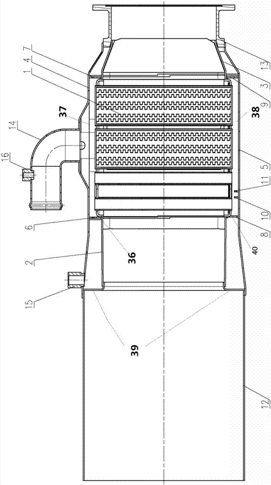
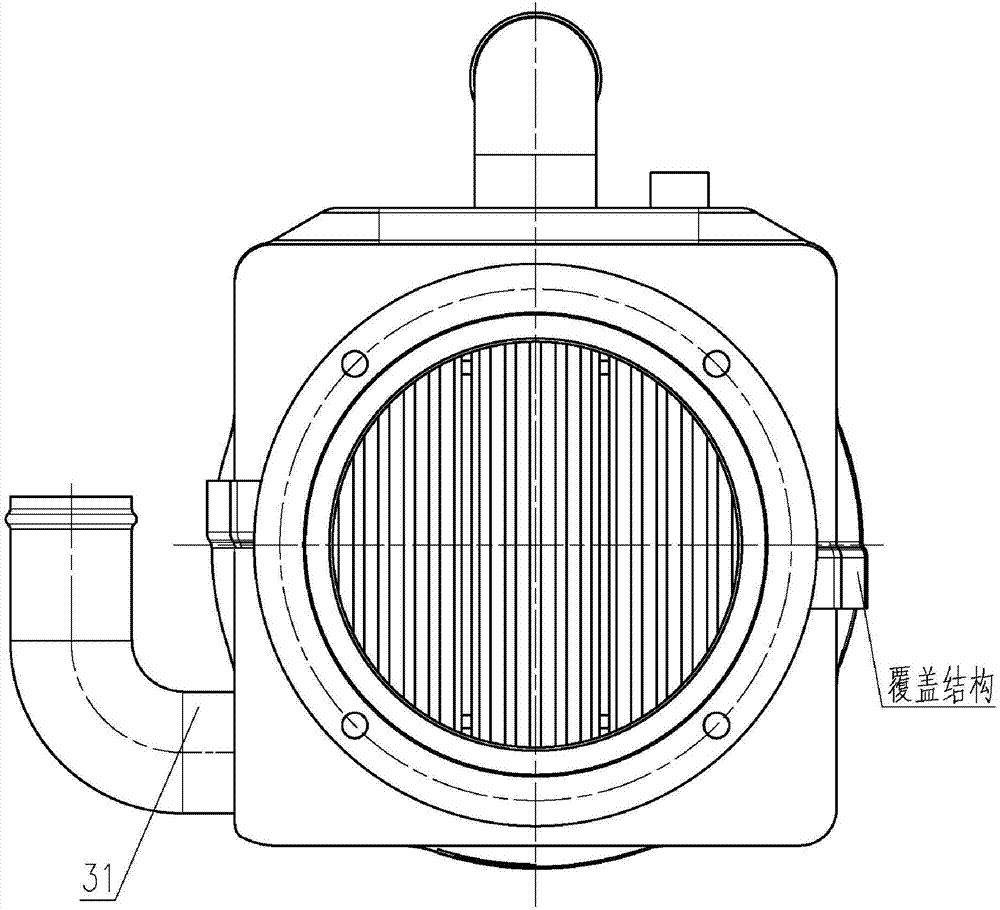
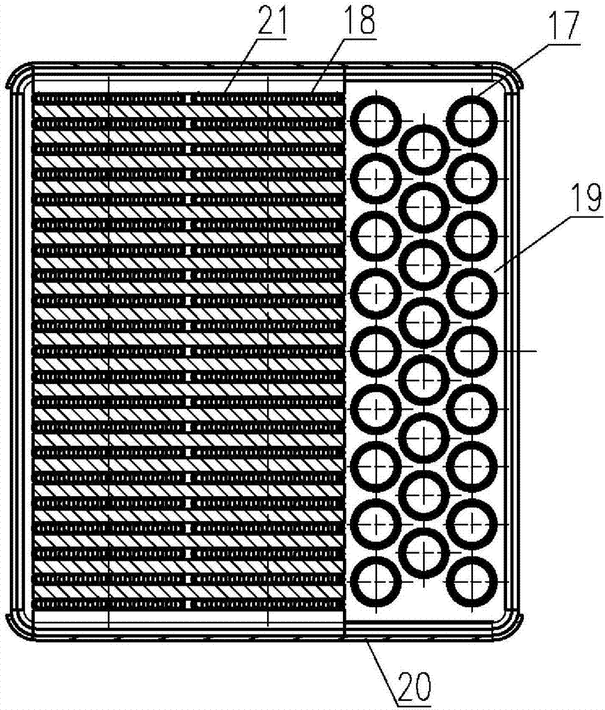
[0049] like Figure 1-6 The shown exhaust gas waste heat utilization heat exchange device includes a heat exchange core 1, a front support 2 of the heat exchange core, and a rear support 3 of the heat exchange core. The heat exchange core 1, the front support 2 and the The rear support body 3 is arranged in the exhaust gas flue 12. The heat exchange core 1 includes an upper cover plate 36, a lower cover plate 40 and a plurality of heat exchange tubes, and the heat exchange tubes are connected through the upper cover plate 36 and the lower cover plate 40. , the front support body 2 and the rear support body 3 are respectively located at both ends of the heat exchange core body 1, and together wit...


PUM


Abstract

The invention provides a heat exchange device utilizing combustion waste heat. The heat exchange device comprises a heat exchange core; the heat exchange core is arranged in a waste gas flue and comprises circular tubes; the circular tubes are arranged perpendicular to the flowing direction of waste gas; a plurality of scattered heat exchange structures are arranged in the round tube at intervals; a plurality of dispersion heat exchange structures are arranged in the circular tubes in a segmented mode in the flow direction of fluid in the circular tubes; the distances between every two adjacent dispersion heat exchange structures become smaller and smaller from inlets of the circular tubes to outlets of the circular tubes. The heat exchange device has the advantages that the distances of the dispersion heat exchange structures in the circular tubes is continuously decreased along with the distance from the inlets of the circular tubes, and therefore the film boiling phenomenon on the water side can be effectively reduced, the convective heat exchange intensity of the water side can be increased, the heat load of the heat exchange core can be reduced, and the heat exchange efficiency can be improved.

Description

technical field [0001] The invention belongs to the field of heat exchange, and in particular relates to a shell-and-tube heat exchange device for waste heat utilization. Background technique [0002] In the past ten years, due to the shortage of energy sources, with the further development of energy conservation work. A variety of new, energy-saving and advanced furnace types are becoming more and more perfect, and the use of high-quality insulation materials such as new refractory fibers has significantly reduced the heat dissipation loss of the furnace. The advanced combustion device is used to strengthen the combustion, reduce the amount of incomplete combustion, and the air-fuel ratio tends to be reasonable. However, the technology of reducing the heat loss of flue gas and recovering the waste heat of flue gas is still not progressing fast. In order to further improve the thermal efficiency of the kiln and achieve the purpose of saving energy and reducing consumption,...

Claims


Application Information

Patent Timeline
Patent Type & Authority Applications(China)
IPC IPC(8): F28D7/16F28F1/00F28F9/013F28F1/02
CPCF28D7/16F28F1/00F28F1/006F28F1/02F28F9/013
Inventor 吕志鸿胡煦东王东杰刘海涛靳雁松贾川贾大鹏李源浩
Owner CHINA NORTH VEHICLE RES INST
Why Eureka
Try Eureka