Visual processing-based screw mounting device and screw mounting method

A technology for installing devices and screws, which can be used in measuring devices, optical devices, instruments, etc., and can solve problems such as large labor input

Pending Publication Date: 2017-10-20
深圳市威富智能设备有限公司
View PDF8 Cites 5 Cited by
  • Summary
  • Abstract
  • Description
  • Claims
  • Application Information

AI Technical Summary

Problems solved by technology

[0004] Aiming at the deficiencies of the prior art, the present invention provides a screw installation device and a screw installation method based on visual processing to make up for the defect in the prior art that the screw machine does not have a self-inspection function, which leads to a large amount of manpower input in the later stage

Method used


Image

  • Visual processing-based screw mounting device and screw mounting method
  • Visual processing-based screw mounting device and screw mounting method
  • Visual processing-based screw mounting device and screw mounting method

Examples


Embodiment

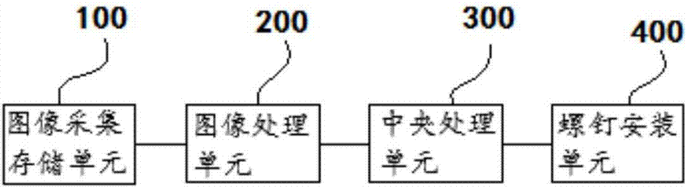
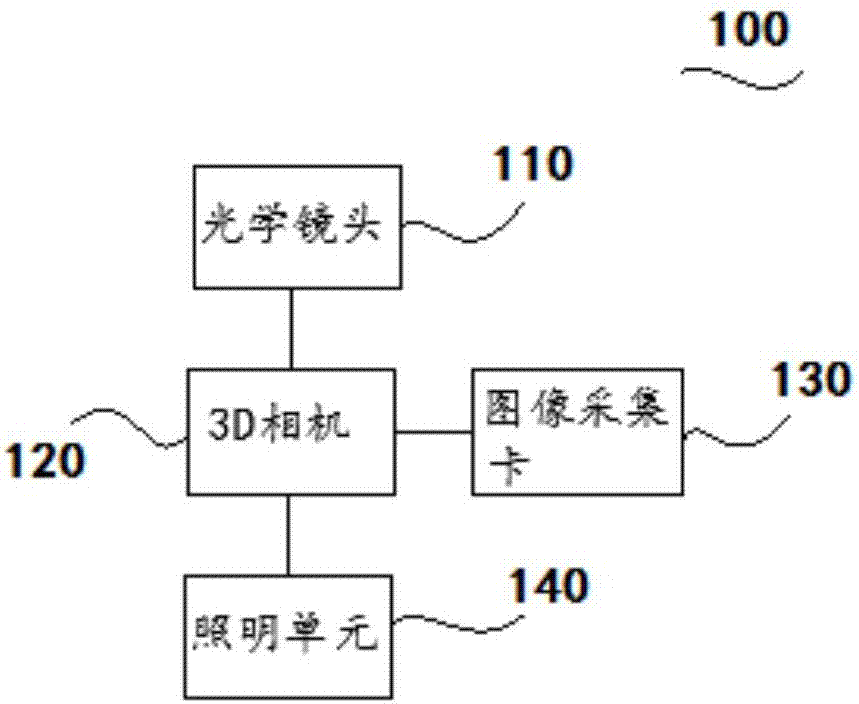
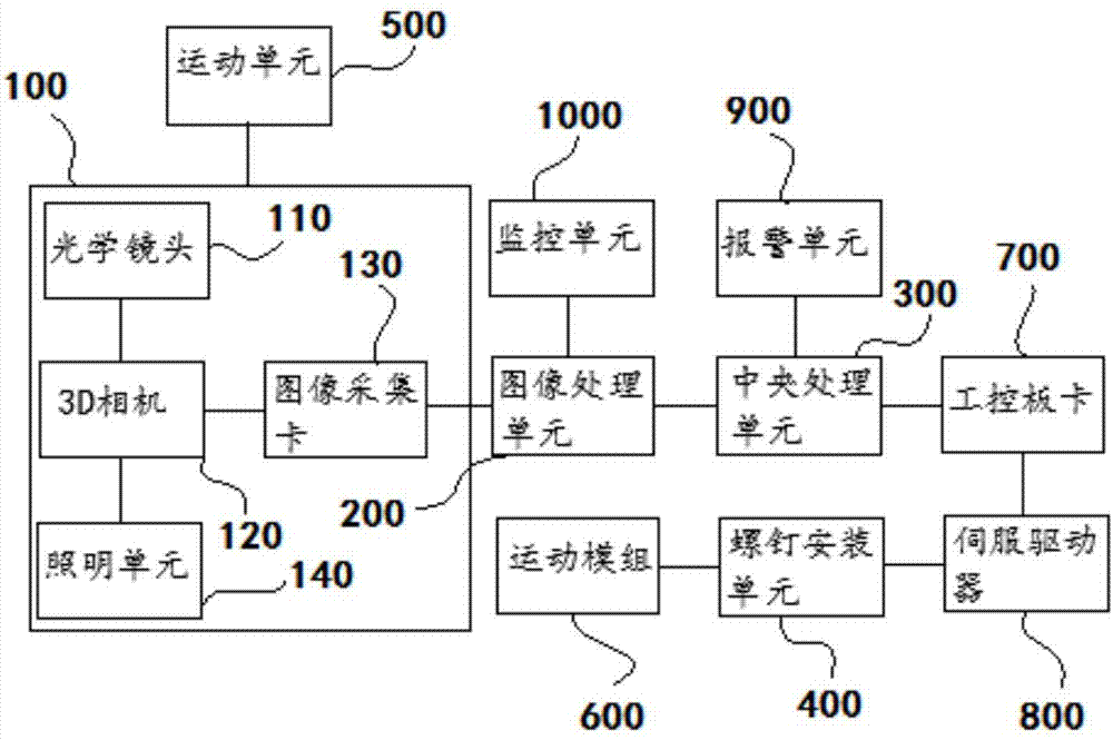
[0039] This embodiment provides a screw installation device based on visual processing, please refer to figure 1 , the screw installation device includes an image acquisition and storage unit 100 , an image processing unit 200 , a central processing unit 300 and a screw installation unit 400 .

[0040] Wherein, the image acquisition and storage unit 100 is used to acquire the image information of the screw and the spatial position of the screw hole. The image processing unit 200 is used to convert image information into digital signals. The central processing unit 300 is used for receiving digital signals and sending operation signals. The screw installation unit 400 is used for receiving an operation signal, and installing screws in corresponding screw holes according to the operation signal.

[0041] In this way, since the image acquisition and storage unit 100 can obtain the image information of the spatial position of the screw and the screw hole, it is possible to obtai...

Embodiment approach

[0071] Specifically, in order to further improve the installation accuracy of the screws, please refer to Figure 5 , another embodiment may include the following steps:

[0072] S100. Acquiring image information of the screw and the spatial position of the screw hole;

[0073] S200. Convert the image information into a digital signal;

[0074] S300. Receive the digital signal and send an operation signal;

[0075] S500. Receive the operation signal, and convert the operation signal into a specific pulse signal;

[0076] S600. Receive the pulse signal, and plan the traveling route of the screw according to the pulse signal, and install the screw in the corresponding screw hole position.

[0077] In this way, the movement trajectory of the screw can be accurately guided through the specific planning of the travel signal of the screw, and the screw can be transported to the designated screw hole position. Moreover, when the position of the screw deviates, real-time adjustmen...


PUM


Abstract

The present invention discloses a visual processing-based screw mounting device and screw mounting method. The visual processing-based screw mounting device includes an image acquisition and storage unit, an image processing unit, a central processing unit and a screw mounting unit; the image acquisition and storage unit is used for obtaining the image information of the spatial positions of screws and screw holes; the image processing unit is used for converting the image information into digital signals; the central processing unit is used for receiving the digital signals and transmitting operation signals; and the screw mounting unit is used for receiving the operation signals and mounting the screws into the screw holes according to the operation signals. Thus, when the screws are mounted, and after the screws are mounted, the height information of the screws can be obtained, and therefore, whether the screws are mounted in place can be determined, and the screw mounting device has a self-detection function, and manpower for detecting whether the screws are mounted in place in a later stage can be saved.

Description

technical field [0001] The invention relates to the technical field of screw locking, in particular to a screw installation device and a screw installation method based on visual processing. Background technique [0002] The assembly line of the product often needs to assemble a large number of screws. In the past, manual work was used, resulting in frequent occurrence of missing screws, and the quality of screw locks cannot be guaranteed, and the product may loose screws in the follow-up work. As a result, signal leakage occurs and the performance of the product is greatly reduced. [0003] Based on this, a screw machine based on visual recognition has appeared in the prior art. The screw machine is mainly based on a CCD camera. Through image acquisition and recognition, the position of the rotational offset of the assembly object is obtained, and then these position coordinates are processed accordingly. Pass it to the corresponding controller to guide the work of the scr...

Claims


Application Information

Patent Timeline
Patent Type & Authority Applications(China)
IPC IPC(8): G01B11/00
CPCG01B11/002
Inventor 张少林关航健王胜
Owner 深圳市威富智能设备有限公司
Why Eureka
Try Eureka