Non-contact bow net arcing detection system

A detection system, non-contact technology, applied in the direction of testing the dielectric strength, using optical methods to test, etc., can solve the problems of high system cost, affecting the detection sensitivity of the system, and the weak discharge point cannot be effectively detected, etc., to achieve The effect of improving detection sensitivity, reducing production cost, and ensuring safety

Pending Publication Date: 2018-03-16
SHENZHEN INST OF ADVANCED TECH CHINESE ACAD OF SCI
View PDF9 Cites 5 Cited by
  • Summary
  • Abstract
  • Description
  • Claims
  • Application Information

AI Technical Summary

Problems solved by technology

[0003] The existing non-contact pantograph-catenary arc detection system has the following problems: (1) the system cost is high
The method of directly converting the ultraviolet light signal into an electrical signal will cause the weak discharge point to not be effectively detected, thus affecting the detection sensitivity of the system
(3) The system does not have a self-test function, and cannot detect whether the system itself can operate normally at any time

Method used


Image

  • Non-contact bow net arcing detection system
  • Non-contact bow net arcing detection system
  • Non-contact bow net arcing detection system

Examples


Embodiment 1

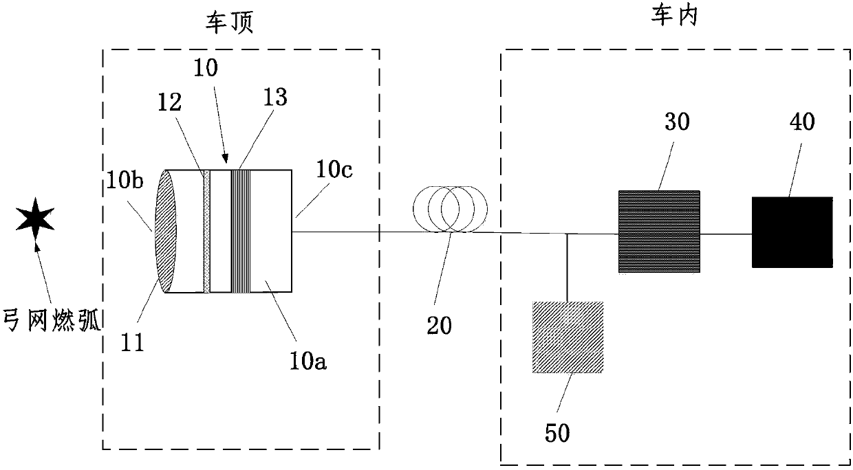
[0028] figure 1 It is a schematic structural diagram of a non-contact pantograph-catenary arc detection system according to Embodiment 1 of the present invention.

[0029] refer to figure 1 , The non-contact pantograph-catenary arc detection system according to the embodiment of the present invention includes: a light collection and conversion device 10 , an optical fiber 20 , a photoelectric conversion circuit 30 , a signal processing device 40 , and a self-test signal generating device 50 . The light collection and conversion device 10 is installed outside the roof of the train. The photoelectric conversion circuit 30, the signal processing device 40, and the self-test signal generating device 50 are installed in the train car.

[0030] The light collection and conversion device 10 is used to focus received light and to convert ultraviolet light into visible light. In this embodiment, converting the ultraviolet light into a visible light signal and performing detection ca...

Embodiment 2

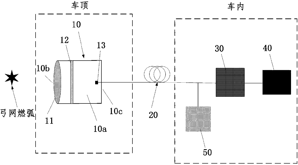
[0047] figure 2 It is a schematic structural diagram of a non-contact pantograph-catenary arc detection system according to Embodiment 2 of the present invention.

[0048] refer to figure 2 , the difference from Embodiment 1 is that the fluorescent layer 13 is disposed on the optical fiber 20 .

[0049] Specifically, in this embodiment, the optical fiber 20 extends into the receiving cavity 10a, the optical fiber 20 includes a light incident surface relative to the filter 12, and the fluorescent layer 13 is attached to the onto the glossy surface. It can be seen that the solution of this embodiment can not only fully convert the ultraviolet light incident on the optical fiber 20 into visible light, but also reduce the amount of the fluorescent layer 13 and reduce the cost.

Embodiment 3

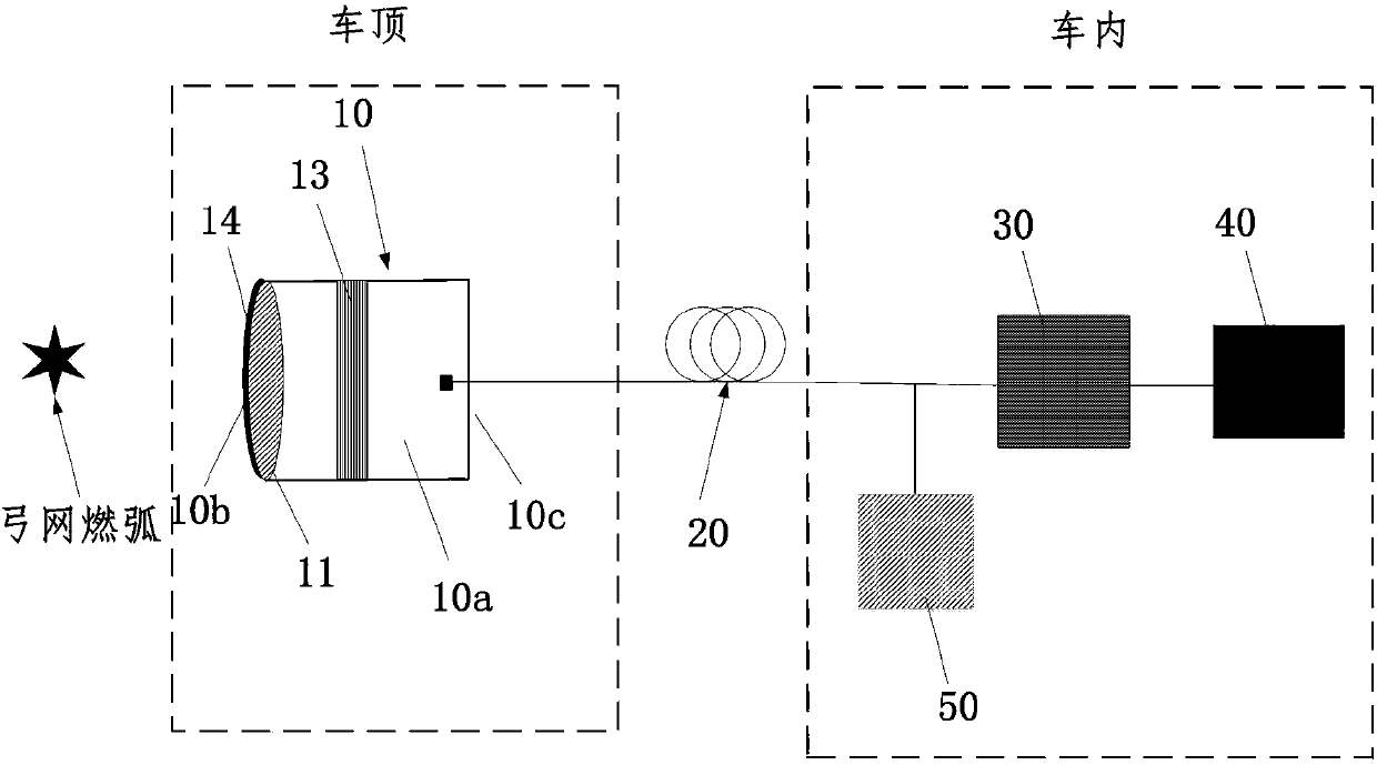
[0051] image 3 It is a schematic structural diagram of a non-contact pantograph-catenary arc detection system according to Embodiment 3 of the present invention.

[0052] refer to image 3 , different from Embodiment 1, the light collection and conversion device 10 of this embodiment does not include a filter 12 .

[0053] Specifically, in this embodiment, the light collection and conversion device 10 includes an optical lens 11 , an optical film 14 disposed on the surface of the optical lens 11 , and a fluorescent layer 13 .

[0054] The housing cavity 10a has a bottom end 10c opposite to the open end 10b, the optical fiber 20 is connected to the bottom end 10c, and the fluorescent layer 13 is disposed between the bottom end 10c and the optical lens 11 .

[0055] The optical film 14 is used to filter the received light to obtain ultraviolet light. Further, the optical film 14 can transmit ultraviolet light but cut off visible light.

[0056] The optical lens 11 is used t...


PUM


Abstract

The invention discloses a non-contact bow net arcing detection system. The system includes a light collection and conversion device used for focusing received light and converting ultraviolet light tovisible light; a photoelectric conversion circuit used for converting the visible light to electric signals; a signal processing device use for judging arcing strength according to the detected electric signals and performing positioning and recording; a self-check signal generating device used for generating self-check visible light signals. The light collection and fluorescent light conversiondevice is also used for collecting the self-check visible light signals. The photoelectric conversion circuit is also used for converting the self-check visible light signals to self-check electric signals. The signal processing device is also used for detecting whether the self-check electric signals are received or not. According to the invention, the detection flexibility of the system is improved, system operation safety is ensured and product cost is reduced substantially.

Description

technical field [0001] The invention belongs to the technical field of catenary detection, and in particular relates to a non-contact pantograph-catenary arc detection system. Background technique [0002] With the development of my country's high-speed railway, the regular detection of the operation status of pantograph-catenary system is of great significance to the safety of my country's railway operation and the development of the national economy. The pantograph-catenary arcing state can comprehensively reflect the dynamic contact performance of the pantograph-catenary system, which is the focus of the pantograph-catenary state detection system. Realizing efficient, accurate and economical pantograph-catenary arc non-contact detection device is an important problem urgently needed to be solved in pantograph-catenary arc detection. When the pantograph is off-line, sparks and arcs are generated, and intense ultraviolet light is emitted at the same time. Arc detection ba...

Claims


Application Information

Patent Timeline
Patent Type & Authority Applications(China)
IPC IPC(8): G01R31/12
CPCG01R31/1218
Inventor 董玉明章逸舟焦国华吕建成鲁远甫罗阿郁
Owner SHENZHEN INST OF ADVANCED TECH CHINESE ACAD OF SCI
Why Eureka
Try Eureka