Backlight module and display device

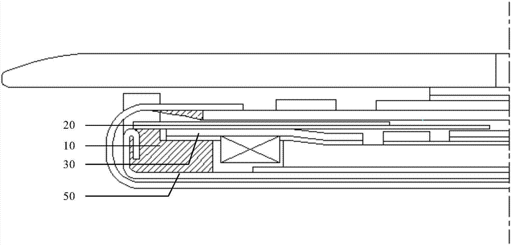
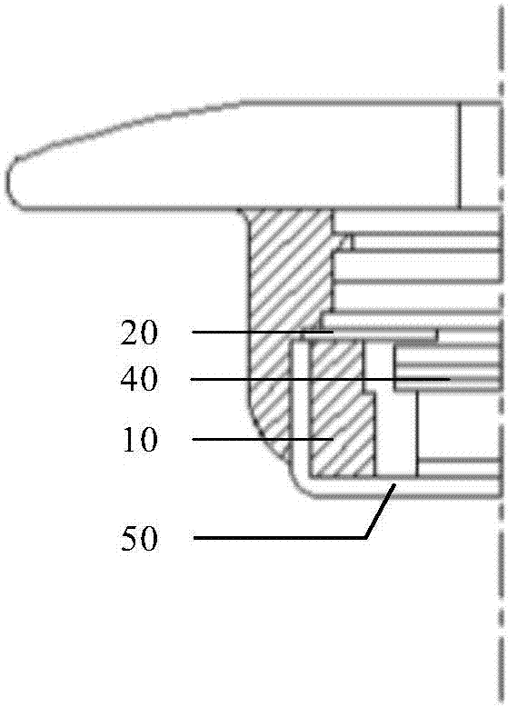
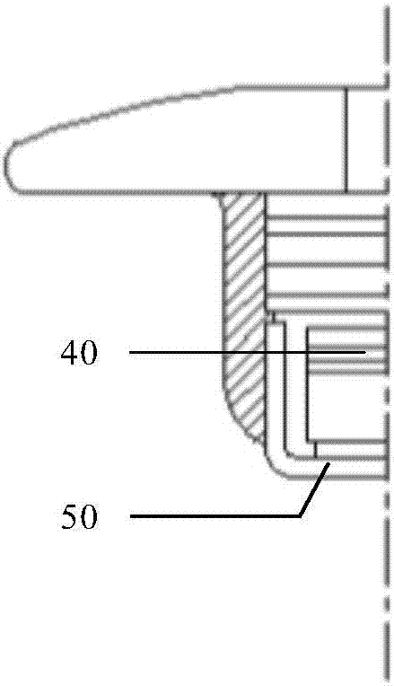
A technology for a backlight module and a display device, which is applied in the directions of light guides, optics, and optical components, can solve the problems of increasing and decreasing the flatness of the backplane 50, saving production costs, improving the flatness, and narrowing the The effect of border width

Inactive Publication Date: 2017-10-20
BOE TECH GRP CO LTD +1
View PDF5 Cites 18 Cited by
  • Summary
  • Abstract
  • Description
  • Claims
  • Application Information

AI Technical Summary

Problems solved by technology

The upper and lower sides are provided with light-shielding tapes 20, on the one hand in order to block the edge bright lines of the optical film material 40, and on the other hand for fixing the optical film material 40 to prevent the film material from shifting or falling off caused by backlight incoming materials, and then On the one hand, it is also to ensure that when the backlight module is pasted and glued, the backplane will be prevented from shifting due to the adhesion between the backplane 50 and FOG (Flexible Printed Circuit on Glass, the flexible circuit board is assembled on the glass substrate). Thus affecting the accuracy of gluing
[0004] However, in the conventional iron-plastic integrated backlight module structure, after the injection molding of the backplane 50, the flatness of the backplane 50 will increase due to the shrinkage and deformation of the plastic frame 10 during molding, so a subsequent leveling process is required. to reduce its flatness

Method used


Image

  • Backlight module and display device
  • Backlight module and display device
  • Backlight module and display device

Examples


Embodiment Construction

[0047]Example embodiments will now be described more fully with reference to the accompanying drawings. Example embodiments may, however, be embodied in many forms and should not be construed as limited to the examples set forth herein; rather, these embodiments are provided so that this disclosure will be thorough and complete, and will fully convey the concept of example embodiments to those skilled in the art. The described features, structures, or characteristics may be combined in any suitable manner in one or more embodiments. In the following description, numerous specific details are provided in order to give a thorough understanding of embodiments of the present disclosure. However, those skilled in the art will appreciate that the technical solutions of the present disclosure may be practiced without one or more of the specific details being omitted, or other methods, components, devices, steps, etc. may be adopted. In other instances, well-known technical solution...


PUM


Abstract

The invention provides a backlight module and a display device, and relates to the technical field of display. The backlight module comprises a back plate and a light source; the back plate comprises a back plate body and a first bending structure perpendicular to the back plate body; on one side of the light source, the back plate further comprises a second bending structure which is connected with the first bending structure and extends in the same direction as the back plate body; the second bending structure comprises a plurality of protrusions arranged at intervals, and concave portions between the adjacent protrusions are used for containing light-emitting parts of the light source. A rubber frame does not need to be arranged, the width of the frame can be reduced, and the flatness of the back plate can be improved.

Description

technical field [0001] The present disclosure relates to the field of display technology, in particular to a backlight module and a display device. Background technique [0002] With the rapid development of electronic technology, people have higher and higher requirements for electronic products. Taking smart phones as an example, the narrow bezel design of the mobile phone screen can make the product more fashionable, and to a certain extent, it can also increase the screen ratio of the screen, making the picture wider, so as to meet consumers' increasing demand for display products. need. [0003] In recent years, the frame size of the mobile phone screen has been reduced to 0.5mm, which puts forward higher requirements for the narrow frame design of the backlight module. At present, for the screen frame below 0.6mm, the backlight module mainly adopts the iron-plastic integrated design. Figure 1 to Figure 3 It is a partial design drawing of an iron-plastic integrated b...

Claims


Application Information

Patent Timeline
Patent Type & Authority Applications(China)
IPC IPC(8): G02F1/13357
CPCG02F1/1336G02F1/133603G02F1/133608G02B6/002G02B6/0055G02B6/009G02B6/0086G02F1/133308G02F1/133314
Inventor 项得胜王彦明王甲强常橙刘蕊刘帅南
Owner BOE TECH GRP CO LTD
Why Eureka
Try Eureka