Coil component

A technology of coil components and wires, applied in transformer/inductor parts, electrical components, transformer/inductor coil/winding/connection, etc. Effects of Transform Properties

Inactive Publication Date: 2017-10-20
MURATA MFG CO LTD
View PDF10 Cites 15 Cited by
  • Summary
  • Abstract
  • Description
  • Claims
  • Application Information

AI Technical Summary

Problems solved by technology

That is, from Comparative Example 2, compared with Comparative Example 1, it is easy to infer that although the number of turns of the wire assembly part 44 is large and a higher inductance value can be obtained, it can be seen that the mode conversion characteristic is greatly deteriorated.

Method used


Image

  • Coil component
  • Coil component
  • Coil component

Examples


no. 1 approach

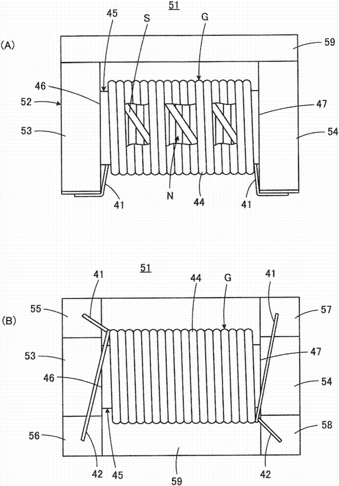
[0063] refer to figure 1 and figure 2 The common mode choke coil 51 as a coil component according to the first embodiment of the present invention will be described. In addition, in figure 1 and figure 2 , against the above Figure 17 ~ Figure 19 Elements corresponding to the elements shown are denoted by the same reference numerals.

[0064] The common mode choke coil 51 includes a drum-shaped core 52 and first and second wires 41 and 42 respectively constituting an inductor. exist figure 1 In the illustration, only the respective ends of the first and second wires 41, 42 are shown, and the middle part is schematically illustrated in a single wire state for reference. Figure 17 The wire assembly part 44 which consists of the 1st wire 41 and the 2nd wire 42 as mentioned above. The drum core 52 is made of an electrically insulating material, more specifically, a non-magnetic material such as aluminum, a magnetic material such as Ni—Zn-based ferrite, or resin. The ...

no. 2 approach

[0113] Next, refer to Figure 6 A common mode choke coil 51a according to a second embodiment of the present invention will be described. exist Figure 6 and later Figure 8 ~ Figure 15 in, right with figure 2 Components corresponding to the shown components are denoted by the same reference numerals, and repeated explanations are omitted.

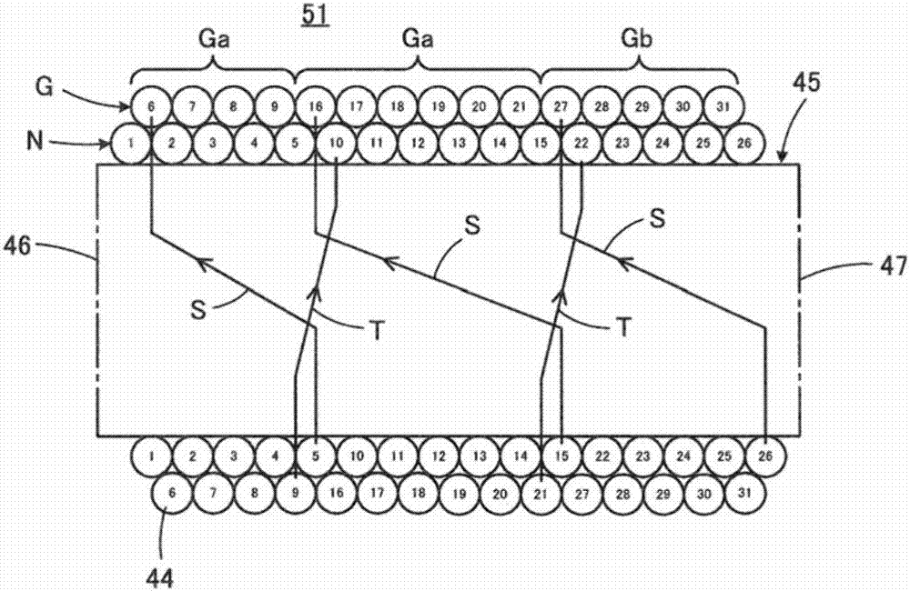
[0114] The common mode choke coil 51a has a larger number of turns of the wire assembly part 44 than the common mode choke coil 51 described above. That is, the number of turns is 37. In addition, in the common mode choke coil 51 , there are three outward transition portions S around the winding core portion 45 , but in the common mode choke coil 51 a, there are five outward transition portions S. Therefore, in the common mode choke coil 51a, five outer layer portions G are formed, more specifically, four first outer layer portions Ga and one second outer layer portion Gb are formed.

[0115] Regarding the common mode choke coil 51a...

no. 3 approach

[0123] Next, refer to Figure 8 The common mode choke coil 51b of the third embodiment of the present invention will be described.

[0124] Common mode choke coil 51b, for example with figure 2 Compared with the common mode choke coil 51 shown, although the number of turns of the wire assembly part 44 is the same, the numbers of the outward transition part S and the inward transition part T are larger.

[0125] Regarding the common mode choke coil 51b, the winding form of the wire assembly part 44 will be described based on the number of turns of the wire assembly part 44 on the winding core part 45. First, the inner layer part N is composed of turns 1 to 2, and then , the transition part from turn 2 to turn 3 constitutes the outward transition part S, then, the first outer layer part Ga is formed by turn 3, and then the transition part from turn 3 to turn 4 constitutes the inward transition part T.

[0126] Next, an inner layer portion N is formed by turns 4-5, then an out...


PUM

PropertyMeasurementUnit
inductanceaaaaaaaaaa

Abstract

The invention provides a coil component. In a common mode choking coil as an example of the coil component, excellent model conversion characteristics can be guaranteed even the number of turns of wires is increased for obtaining high inductance. A wire assembly portion (44) formed by twisting two wires is wrapped around a winding core portion (45). The wire assembly portion (44) comprises an inner layer portion (N) that is in contact with and wound around the circumferential surface of the winding core portion with a first end portion (46) as the initial end, an outer layer portion (G) wound around the outer circumference of the inner layer portion, outward transition portions each extending from the inner layer portion to the outer layer portion, and an inward transition portion extending from the outer layer portion to the inner layer portion. The wire assembly portion is lead out from the middle position in the winding center axis direction of the inner layer portion by means of the outward transition portions to form the outer layer portion and returns to the middle position of the inner layer portion by means of the inward transition portion.

Description

technical field [0001] The present invention relates to a coil component, and particularly relates to a coil component having a structure in which two wires in a twisted state are wound around a winding core. Background technique [0002] A typical example of the coil component to which the present invention is directed is a common mode choke coil. [0003] For example, in Japanese Patent Application Laid-Open No. 2014-207368 (Patent Document 1) and Japanese Patent No. 5558609 (Patent Document 2), it is described that a wire assembly in which two wires are twisted is wound around a winding core. A common mode choke coil is formed. [0004] Patent Document 1: Japanese Patent Laid-Open No. 2014-207368 [0005] Patent Document 2: Japanese Patent No. 5558609 [0006] The inventors of the present application have studied as a future technology to improve the mode conversion characteristics by using a structure in which a wire assembly part in a twisted state is wound, and to a...

Claims


Application Information

Patent Timeline
Patent Type & Authority Applications(China)
IPC IPC(8): H01F17/04H01F27/24H01F27/30H01F27/29
CPCH01F17/045H01F27/24H01F27/292H01F27/306H01F2017/0093H01F2027/2838H01F3/10H01F27/29H01F27/2823
Inventor 桥本良太前田昌祯山口千寻郑裕行小林耕平
Owner MURATA MFG CO LTD
Why Eureka
Try Eureka