
brushless motor

A motor and housing technology, applied in the field of brushless motors, can solve problems such as difficult to ensure space, and achieve the effect of smooth assembly

Active Publication Date: 2019-05-14
MABUCHI MOTOR
View PDF9 Cites 0 Cited by
  • Summary
  • Abstract
  • Description
  • Claims
  • Application Information

AI Technical Summary

Problems solved by technology

This space is used, for example, when there is a requirement for waterproofing or a requirement for fixing the lead-out position of the lead wire, but adding positioning parts will make it difficult to secure the space, and there is a problem that it cannot meet these requirements anymore.

Method used


Image

  • brushless motor
  • brushless motor
  • brushless motor

Examples


Embodiment Construction

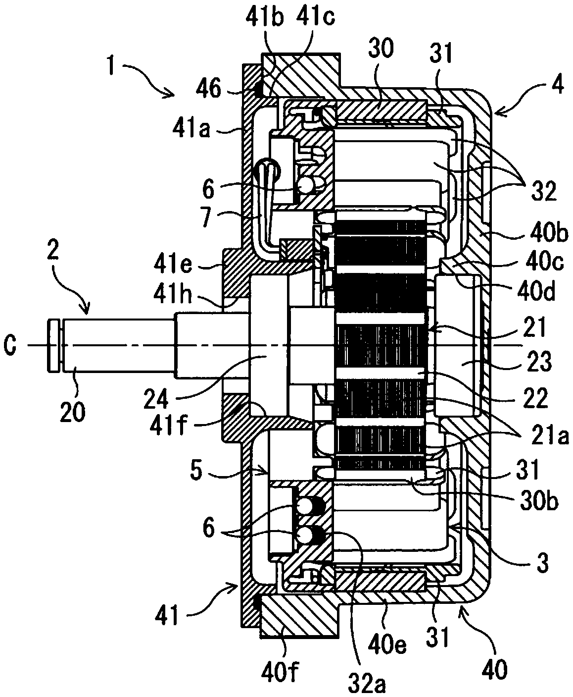
[0029] A brushless motor as an embodiment will be described with reference to the drawings. The embodiments shown below are examples at most, and it is not intended to exclude various modifications and technical applications not explicitly described in the following embodiments. Each structure of this embodiment can be implemented with various modifications within the range which does not deviate from the gist. In addition, trade-offs can be made as needed, or combinations can be made as appropriate. In the following description, the axial direction of the motor is also referred to as a "vertical direction". In addition, the bottom side of the case is described as "downward", and the opening side of the case is described as "upper".

[0030] [1. Composition]

[0031] [1-1. Overall composition]

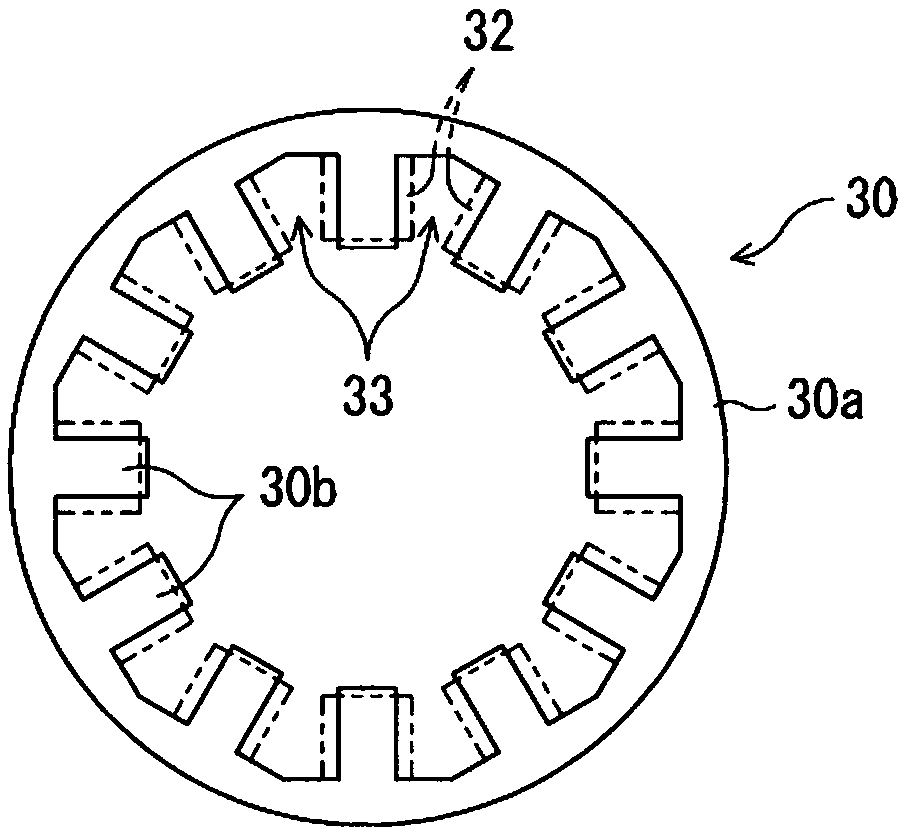
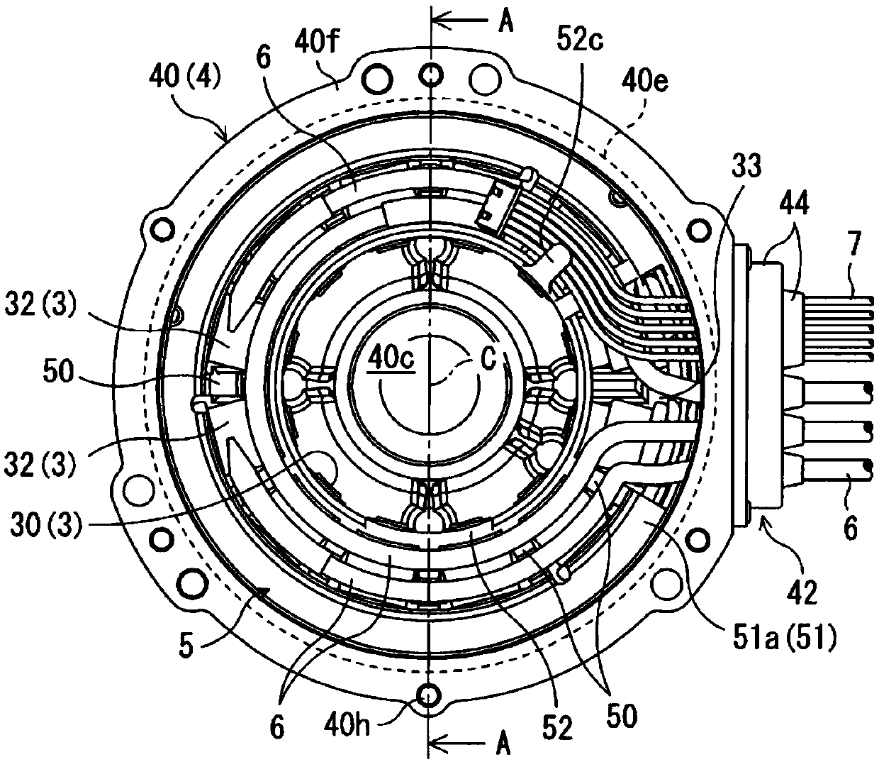
[0032] figure 1 It is an axial cross-sectional view of a brushless motor 1 (hereinafter referred to as "motor 1") of the present embodiment. The motor 1 is an inner rotor type br...


PUM


Abstract

The present invention regulates the position of the wire and secures the space in the axial direction. The brushless motor of the present invention includes: a stator (3) having a winding (32) wound on the inner peripheral side of an annular stator core (30) protruding through an insulator; on a plurality of teeth; the housing (4), which houses the stator (3); the wires (6), which supply power to the windings (32) from outside the housing (4); and the positioning part (5), which At least one of the casing (4) and the stator (3) is supported inside the body (4), and the wire (6) is extended in the circumferential direction. The positioning part (5) has a predetermined part (50) arranged in the space between the adjacent windings (32) in the circumferential direction, and regulates the position of the lead wire (6).

Description

technical field [0001] The present invention relates to a brushless motor equipped with positioning elements for supporting wires within a housing. Background technique [0002] A brushless motor is a motor that obtains output by controlling the energization of the windings of the stator to rotate the rotor, and supplies power to the windings through a power input wire. The wires are connected to the windings of each phase in the casing and are led out to the outside of the casing, and in the case of unconstrained conditions where these wires are not specially supported or fixed in the casing, there is a risk that the wires overlap each other or enter the center of the stator. The problem of assembly is more troublesome due to the space. [0003] In addition, in addition to the wires for power input, there are also wires for sensor signal input and output to control energization inside the case. Therefore, it is necessary to perform assembly work more carefully when these w...

Claims


Application Information

Patent Timeline
Patent Type & Authority Patents(China)
IPC IPC(8): H02K5/22H02K3/50H02K29/08
CPCH02K3/50H02K5/225H02K29/08
Inventor 岩崎佑哉
Owner MABUCHI MOTOR
Learn More