
A valve rotation mechanism

A technology of rotating mechanisms and valves, applied in mechanical equipment, engine components, machines/engines, etc., can solve problems such as easy formation of carbon deposits, uneven wear, excessive wear of valves, etc., to alleviate carbon deposits and avoid excessive thickness Effect

Active Publication Date: 2019-06-04
CHONGQING CHANGAN AUTOMOBILE CO LTD
View PDF8 Cites 0 Cited by
  • Summary
  • Abstract
  • Description
  • Claims
  • Application Information

AI Technical Summary

Problems solved by technology

[0002] As one of the main parts of the internal combustion engine, the valve not only bears the corrosion of high-temperature gas, but also bears the combined effects of the explosion pressure in the cylinder, the seating force exerted by the valve spring and the thermal stress of the valve disc, and there is excessive wear or unevenness of the valve. Wear problems, in the absence of the necessary lubrication can lead to valve wear and failure
In addition, carbon deposits are easy to form on the valve, which will affect the airtightness of the valve when it is closed.

Method used


Image

  • A valve rotation mechanism
  • A valve rotation mechanism
  • A valve rotation mechanism

Examples


Embodiment Construction

[0018] The present invention will be further described below in conjunction with accompanying drawing.

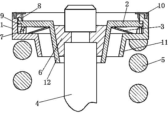
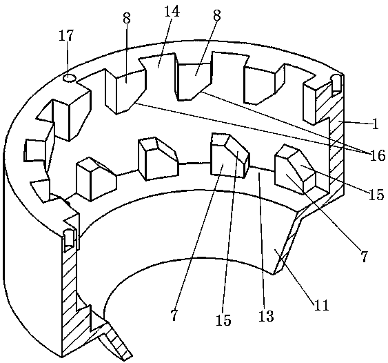
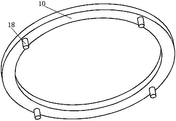
[0019] Such as figure 1 A valve rotating mechanism shown includes a valve stem 4, a rotating member 2 fixedly mounted on the valve stem 4, a valve spring seat 1 sleeved on the periphery of the rotating member 2, and a valve spring 5 pushing upward against the valve spring seat 1; Part 2 comprises a gear part, and the periphery of the gear part is provided with external teeth 9, and the side wall of the external teeth 9 facing the first direction of the circumferential direction of the gear part is provided with an upper inclined surface 20 and a lower inclined surface 19, and the upper inclined surface 20 is from top to bottom along the The first direction is inclined, and the lower slope 19 is inclined toward the first direction from bottom to top; the valve spring seat 1 is provided with a cavity, and the upper and lower ends of the cavity are provided with avoidance open...


PUM


Abstract

The invention relates to a valve rotating mechanism which comprises a valve rod, a rotating part, a valve spring base and a valve spring. The rotating part comprises a gear portion. Outer teeth are arranged on the periphery of the gear portion. The side wall in the first direction, facing the circumferential direction of the gear portion, of the outer teeth is provided with upper inclined faces and lower inclined faces. A cavity is formed in the valve spring base, and the gear portion is located in the cavity. The lower end of the cavity is provided with a lower gear ring capable of being engaged with the gear portion. The lower gear ring is composed of multiple lower teeth. The lower teeth are provided with lower tooth faces corresponding to the lower inclined faces. The upper end of the cavity is provided with an upper gear ring capable of being engaged with the gear portion. The upper gear ring is composed of multiple upper teeth. The upper teeth are provided with upper tooth faces corresponding to the upper inclined faces. The upper teeth and the lower teeth are staggered in the circumferential direction of the valve spring base. A belleville spring which jacks the gear portion upwards is arranged in the cavity. In the vertical direction, the elastic coefficient of the belleville spring is smaller than that of the valve spring. By means of the valve rotating mechanism, a valve can be automatically rotated in the working process.

Description

technical field [0001] The invention relates to an internal combustion engine, in particular to a valve rotation mechanism. Background technique [0002] As one of the main parts of the internal combustion engine, the valve not only bears the corrosion of high-temperature gas, but also bears the combined effects of the explosion pressure in the cylinder, the seating force exerted by the valve spring and the thermal stress of the valve disc, and there is excessive wear or unevenness of the valve. The problem of wear, in the absence of the necessary lubrication, will lead to valve wear and failure. In addition, carbon deposits are easy to form on the valve, which will affect the air tightness of the valve when it is closed. Contents of the invention [0003] The purpose of the present invention is to provide a valve rotation mechanism to make the valve rotate automatically during operation. [0004] A valve rotating mechanism according to the present invention, comprising ...

Claims


Application Information

Patent Timeline
Patent Type & Authority Patents(China)
IPC IPC(8): F01L1/32F01L3/24
CPCF01L1/32F01L3/24
Inventor 肖祥詹樟松蒋继科林翰徐丽茹伍建撰薛东升
Owner CHONGQING CHANGAN AUTOMOBILE CO LTD
Learn More