Wind energy facility with drive train

A technology for wind power generation equipment and drive trains, which is applied to wind power generation, wind turbines, mechanical equipment, etc., and can solve problems such as high consumption and unfavorable connections.

Inactive Publication Date: 2017-10-24
森维安有限公司
View PDF8 Cites 4 Cited by
  • Summary
  • Abstract
  • Description
  • Claims
  • Application Information

AI Technical Summary

Problems solved by technology

However, corresponding connections are disadvantageous because they are generally complex to produce due to the torques to be transmitted

Method used


Image

  • Wind energy facility with drive train

Examples


Embodiment Construction

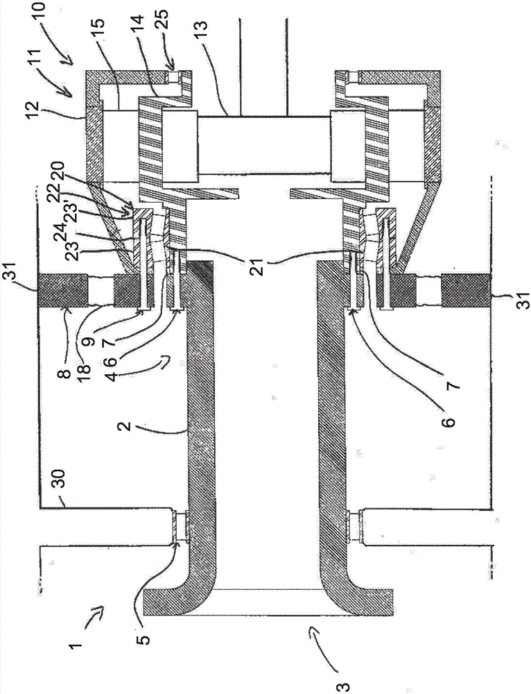
[0028] figure 1 A drive train 1 of a wind power plant according to the invention with components relevant to the invention is schematically shown in .

[0029] The drive train 1 comprises a rotor shaft 2 to which a rotor of the wind power plant can be fastened at an end 3 . A planet gear 10 is arranged at the other end 4 of the rotor shaft. Only the first gear stage 11 of the gear transmission 10 is shown.

[0030] The first gear stage 11 comprises an internally toothed hollow gear 12, an externally toothed sun gear 13 and a planet carrier 14 with orbiting gears 15 arranged thereon as gear parts, which are engaged to the In the toothing of the hollow wheel 12 and in the toothing of the sun wheel 13 . The ring gear 12 is fixedly connected to the gear housing 16 , while the sun gear 13 is mounted rotatably relative to the gear housing 16 via rolling bearings (not shown for the sake of clarity). The support of the planetary carrier 14 in the gear housing 16 via the double-row...


PUM


Abstract

The invention relates to a wind energy facility with a drive train (1). The invention relates to a wind turbine with a drive train (1) comprising a rotor shaft (2) and a planetary gear (10). The rotor shaft (2) is fixed and play-free with the planet carrier (14) of the first gear stage (11). Furthermore, the rotor shaft (2) on the side facing away from the first gear stage (11) side (3) with a roller bearing (5) on a support structure (30) is mounted. The planetary carrier (14) connected to the rotor shaft (2) is mounted with a double-row roller bearing (20) in an X arrangement as a fixed bearing in a transmission housing (16), wherein the transmission housing (16) on at least one opposite the support structure (30 ) fixed support (31) is attached.

Description

technical field [0001] The invention relates to a wind power plant with a drive train comprising a rotor shaft and a planetary gear. Background technique [0002] In known wind power plants, a rotor rotatable about a substantially horizontal axis is rotated by the wind. Here, the rotor is fixedly connected to the rotor shaft and to the generator via a gear transmission, so as to convert the rotational energy of the rotor into electrical energy. [0003] For the rotatable mounting of the rotor, it is known to mount the drive train of the wind power plant in a three-point mounting. Here, the rotor shaft is supported via a front bearing arranged close to the connection area to the rotor and is connected in the rear area to the gear transmission fastened to the frame of the wind power plant. At the two side gear mounts. In a three-point bearing of this type, the rotor shaft is supported on bearings of the gear transmission, in particular with respect to bending loads. [000...

Claims


Application Information

Patent Timeline
Patent Type & Authority Applications(China)
IPC IPC(8): F03D15/00
CPCF03D15/00F05B2260/40311F05B2280/5001F16C2360/31F16H2057/02078F03D80/70F16C35/042F03D15/10Y02E10/72
Inventor 阿尔夫·特雷德
Owner 森维安有限公司
Why Eureka
Try Eureka