
Steel ball type automobile steering intermediate shaft steel ball retainer

A cage and intermediate shaft technology, which is applied to bearing components, shafts and bearings, mechanical equipment, etc., can solve the problems of easy wear of cages, increased material costs, and reduced cleanliness of raceways, so as to improve working conditions and prolong work. Life and contact area reduction effect

Pending Publication Date: 2017-10-24
YUBEI CSA XINXIANG AUTO TECH CO LTD
View PDF9 Cites 0 Cited by
  • Summary
  • Abstract
  • Description
  • Claims
  • Application Information

AI Technical Summary

Problems solved by technology

[0002] The existing steel ball type automobile steering intermediate shaft steel ball cage is generally arranged in a cylindrical shape, and several cylindrical reinforcing ribs are evenly distributed on its surface, and each reinforcing rib has several ball bowls for laying steel balls. , the steel ball is located in the peach-shaped raceway formed by the sleeve shaft and the sleeve, and transmits torque; the main disadvantages of this type of structure are: ①The cylindrical rib on the ball cage and the sleeve shaft and the sleeve form The peripheral clearance of the peach-shaped raceway space is small. When the dimensional accuracy of the peach-shaped raceway is not high enough, there is a possibility of contact between the cylindrical rib and the surface of the peach-shaped raceway, which will make the sleeve shaft relative to the sleeve. Additional friction is generated during axial sliding, which eventually leads to excessive sliding force of the product and increases the work intensity of the assembler; ②There is no grease storage groove on the surface of the steel ball cage, which increases the material cost; ③There is no grease storage groove on the surface, which can be maintained after durability. The frame is easy to wear, the cleanliness of the raceway is reduced, and it is easy to cause the steel ball to slide and get stuck

Method used


Image

  • Steel ball type automobile steering intermediate shaft steel ball retainer
  • Steel ball type automobile steering intermediate shaft steel ball retainer
  • Steel ball type automobile steering intermediate shaft steel ball retainer

Examples


Embodiment Construction

[0010] Embodiments are described in detail in conjunction with the accompanying drawings,

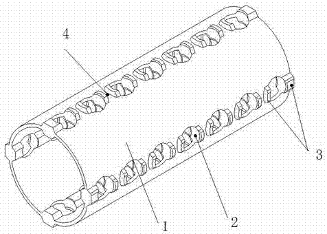
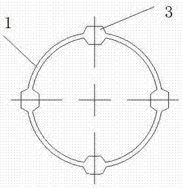
[0011] A steel ball type automobile steering intermediate shaft steel ball cage, which includes a ball bowl 2, a plurality of parallel ball bowls are arranged on the frame body 1 of the steel ball type automobile steering intermediate shaft steel ball cage, and each ball Both sides of the bowl are provided with irregular polygonal ribs 3, and an oil storage tank 4 is left between adjacent polygonal ribs; the polygonal ribs protrude from the surface of the steel ball cage; the polygonal ribs The height of the rib protruding from the surface of the steel ball cage can be selected as 1.75-4 mm, and 2 mm is the best.

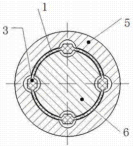
[0012] The present invention utilizes the presence of irregular polygonal reinforcing ribs to increase the space gap between the reinforcing ribs and the peach-shaped raceway formed by the sleeve shaft 6 and the sleeve 5, thus eliminating the problems caused by the lack of pr...


PUM


Abstract

The invention discloses a steel ball type automobile steering intermediate shaft steel ball retainer. According to the technical scheme, the steel ball type automobile steering intermediate shaft steel ball retainer is characterized by comprising ball bowls; the multiple parallel ball bowls are arranged on a frame body of the steel ball type automobile steering intermediate shaft steel ball retainer; irregular polygonal reinforcing ribs are arranged on the two sides of each ball bowl; and an oil storage tank is reserved between every two adjacent polygonal reinforcing ribs. The steel ball type automobile steering intermediate shaft steel ball retainer has the beneficial effects that the purpose of reducing the product sliding force can be achieved, the weight of the retainer is reduced, and the material cost is reduced; the working conditions of the retainer can be improved, and the working life of the retainer is prolonged; and meanwhile, a certain effect of reducing the sliding force also can be achieved due to the fact that the contact area is reduced.

Description

technical field [0001] The invention relates to an automobile steering intermediate shaft, in particular to a steel ball cage suitable for a steel ball type automobile steering intermediate shaft. Background technique [0002] The existing steel ball type automobile steering intermediate shaft steel ball cage is generally arranged in a cylindrical shape, and several cylindrical reinforcing ribs are evenly distributed on its surface, and each reinforcing rib has several ball bowls for laying steel balls. , the steel ball is located in the peach-shaped raceway formed by the sleeve shaft and the sleeve, and transmits torque; the main disadvantages of this type of structure are: ①The cylindrical rib on the ball cage and the sleeve shaft and the sleeve form The peripheral clearance of the peach-shaped raceway space is small. When the dimensional accuracy of the peach-shaped raceway is not high enough, there is a possibility of contact between the cylindrical rib and the surface o...

Claims


Application Information

Patent Timeline
Patent Type & Authority Applications(China)
IPC IPC(8): F16C33/38
CPCF16C33/38
Inventor 张浩洋郭振洲李晓锋魏永辉张铁山
Owner YUBEI CSA XINXIANG AUTO TECH CO LTD
Learn More