Speed reducing assembly

A technology of assembly and reduction mechanism, applied in the direction of gear transmission, belt/chain/gear, mechanical equipment, etc., can solve the problems of large backlash, low precision and efficiency, large backlash, etc., to achieve no backlash, output The effect of high torque accuracy

Active Publication Date: 2017-10-24
高克
View PDF7 Cites 0 Cited by
  • Summary
  • Abstract
  • Description
  • Claims
  • Application Information

AI Technical Summary

Problems solved by technology

[0003] At present, the reduction unit of most planetary gear reducers on the market has the problem of backlash in the meshing of the gears under working conditions, which directly affects the accuracy and efficiency of the reducer. Therefore, the traditional planetary gear reducer has a large hysteresis , and the shortcomings of low precision and efficiency, even if the overall precision of the reducer with this structure is improved or the accuracy can be guaranteed by introducing foreign planetary gear reducers, the production cost is high
[0004] In order to overcome the defect of large backlash in the above-mentioned gear reducer, some reducers use a conical friction wheel structure to achieve the purpose of deceleration, but the conical friction wheel has a large axial force under working conditions, making the structure complicated , and the production efficiency is low, and the production cost is high

Method used


Image

  • Speed reducing assembly
  • Speed reducing assembly
  • Speed reducing assembly

Examples


Embodiment 1

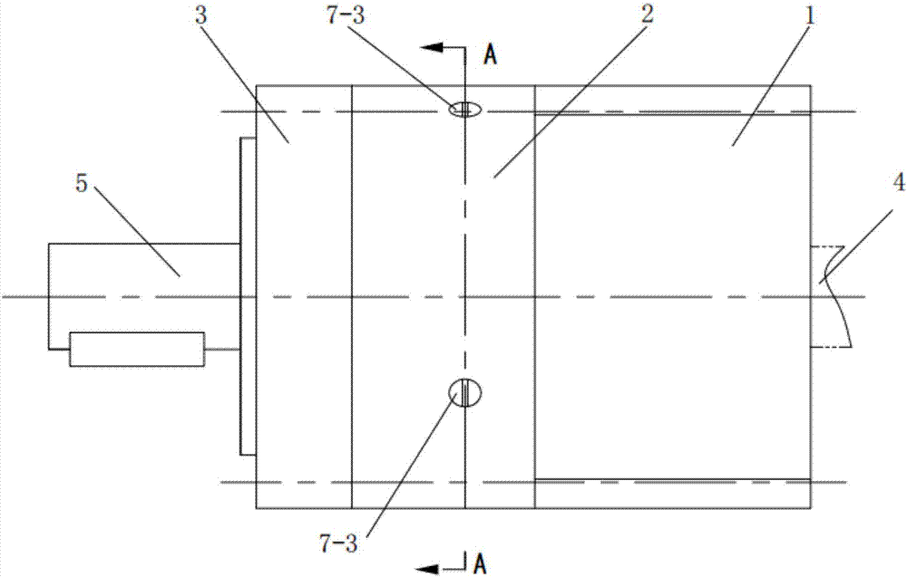
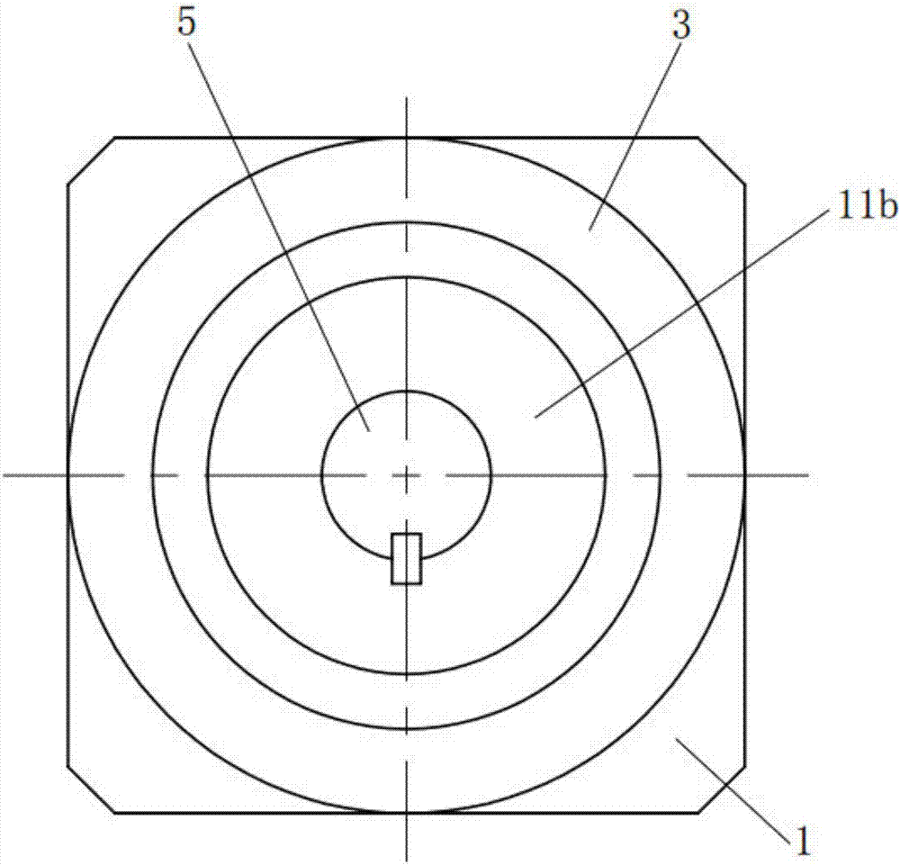
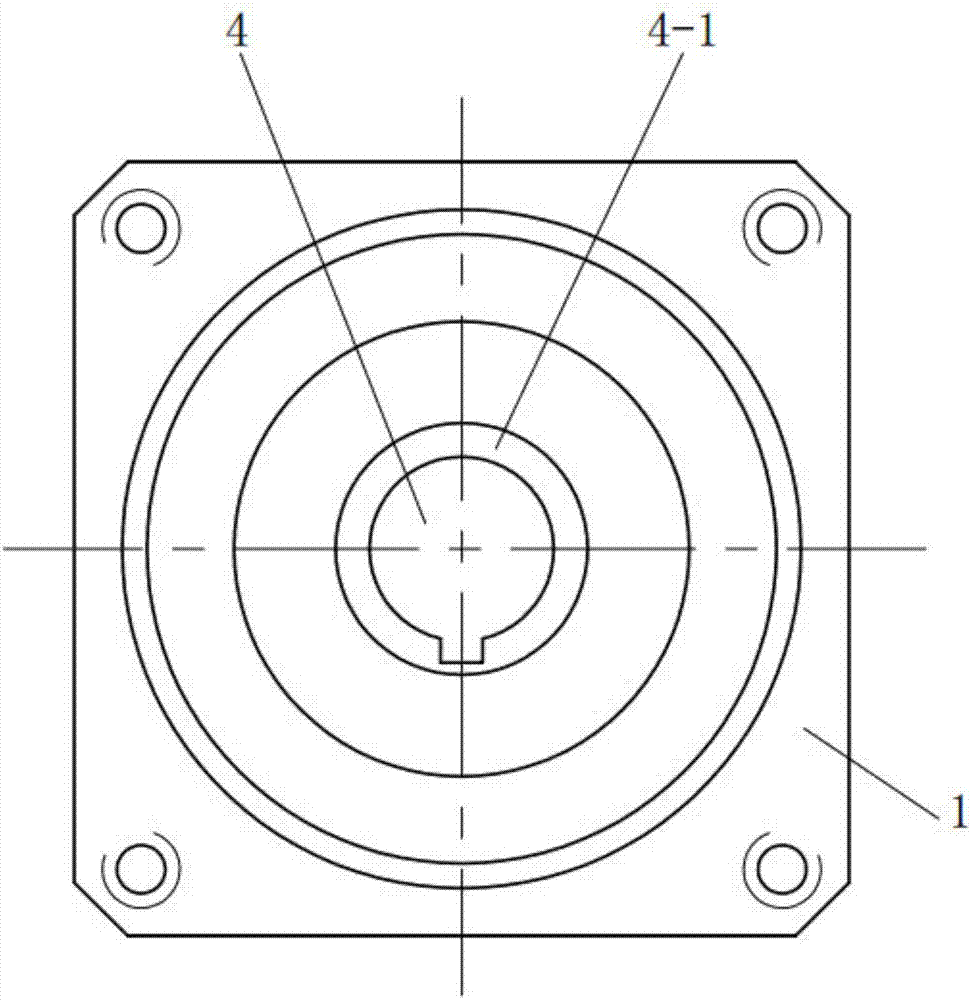
[0038] Such as figure 1 , 2 , 3, 4, 5, and 10, a deceleration assembly, including a deceleration mechanism, an input flange 1, a box body 2, an output flange 3, an input shaft 4, an output shaft 5 and an output indexing plate 5-1 ;

[0039] The input flange 1, the box body 2 and the output flange 3 are connected as a whole by fasteners, and the box body 2 is located between the input flange 1 and the output flange 3, and the output shaft 5 passes through the second rolling bearing 9b Put it into the output flange 3, and the output shaft 5 and the output index plate 5-1 are integrated or fixedly connected with each other, and the speed reduction mechanism is set in the box body 2;

[0040] The reduction mechanism at least includes a first-stage reduction unit, and the first-stage reduction unit includes a first-stage sun friction wheel 8a, a first-stage planetary friction wheel 6a, and a first-stage fine-tunable clamping ring 7a;

[0041] The first-stage sun friction wheel 8...

Embodiment 2

[0053] Such as Figure 6 , 7 , 8, 9, and 10, the difference between embodiment 2 and embodiment 1 is that the reduction mechanism in embodiment 2 also includes a two-stage deceleration unit, and the two-stage deceleration unit includes a two-stage sun friction wheel 8b , two-stage planetary friction wheel 6b and two-stage fine-tuning clamping ring 7b;

[0054] The outer circumference of the secondary sun friction wheel 8b has at least three secondary planetary friction wheels 6b, the secondary sun friction wheel 8b is frictionally connected to the secondary planetary friction wheel 6b, and the secondary planetary friction wheel 6b is connected to the secondary planetary friction wheel 6b The fine-adjustable clamping ring 7b is frictionally connected, and the secondary fine-adjustable clamping ring 7b is fixedly connected to the box body 2;

[0055] The secondary sun friction wheel 8b is in transmission connection with the primary planetary friction wheel 6a, and the secondar...


PUM


Abstract

The invention relates to a speed reducing assembly which comprises a speed reducing mechanism, an input flange, a box body, an output flange, an input shaft, an output shaft and an output index plate. The speed reducing mechanism comprises at least a primary speed reducing unit, wherein the primary speed reducing unit comprises a primary sun friction wheel, a primary planetary friction wheel and a primary fine-adjustable clamping ring. The primary sun friction wheel is provided with an input shaft connecting sleeve, the input shaft is installed in the input shaft connecting sleeve, the input shaft connecting sleeve is installed in the input flange through a first rolling bearing, the periphery of the primary sun friction wheel is provided with at least three primary planetary friction wheels, the primary sun friction wheel is in driving connection with the primary planetary friction wheels and is in driving connection with the primary fine-adjustable clamping ring, the primary fine-adjustable clamping ring is fixedly connected with the box body, and the primary planetary friction wheels are in driving connection with the output index plate. The speed reducing assembly is simple in structure, the production efficiency is improved, and high output precision and low production cost can be ensured.

Description

technical field [0001] The invention specifically relates to a speed reduction assembly. Background technique [0002] The existing deceleration assembly (reducer) is an independent closed transmission device between the prime mover and the working machine, which is used to reduce the speed and increase the torque to meet the work needs. At present, gear reducers, worm gear reducers and planetary gear reducers are widely used in reducers. Different types of motors need to be matched with reducers of different structures to meet the working needs. [0003] At present, the reduction unit of most planetary gear reducers on the market has the problem of backlash in the meshing of the gears under working conditions, which directly affects the accuracy and efficiency of the reducer. Therefore, the traditional planetary gear reducer has a large hysteresis , and the shortcomings of low precision and efficiency, even if the overall precision of the reducer with this structure is imp...

Claims


Application Information

Patent Timeline
Patent Type & Authority Applications(China)
IPC IPC(8): F16H1/32
CPCF16H1/32
Inventor 高克
Owner 高克
Why Eureka
Try Eureka