Four-mass block micromechanical gyroscope capable of being directly coupled in angular rate sensitive direction

A micromachined gyroscope and direction-sensitive technology, which is applied in the direction of speed measurement, gyroscope/steering sensing device, speed/acceleration/shock measurement, etc. due to the gyro effect, which can solve the limitation of the application range of the micromachined gyroscope and the difference in the performance of the micromachined gyroscope. huge and other problems, to achieve the effect of reducing the source of error signals and reducing the difficulty of control

Active Publication Date: 2017-10-24
XIAN FLIGHT SELF CONTROL INST OF AVIC
View PDF10 Cites 6 Cited by
  • Summary
  • Abstract
  • Description
  • Claims
  • Application Information

AI Technical Summary

Problems solved by technology

However, from the perspective of the four-mass micromechanical gyro as a whole, multiple gyro units are independent of each other. Under the vibration excitation of the external environment, the overall driving mode and detection mode have multiple motion modes, but the required driving mode There is only one useful motion for the detection mode and the detection mode, so the interference signal generated by the environmental vibration is bound to be mixed with the angular rate signal sensitive to the micro-mechanical gyroscope, which makes it difficult to separate the performance of the micro-mechanical gyroscope in the static and vibration states. As a result, the application range of micromechanical gyroscopes is greatly limited

Method used


Image

  • Four-mass block micromechanical gyroscope capable of being directly coupled in angular rate sensitive direction
  • Four-mass block micromechanical gyroscope capable of being directly coupled in angular rate sensitive direction
  • Four-mass block micromechanical gyroscope capable of being directly coupled in angular rate sensitive direction

Examples


Embodiment Construction

[0020] The four-mass micromechanical gyroscope directly coupled with angular rate sensitive directions of the present invention will be further described below in conjunction with the accompanying drawings.

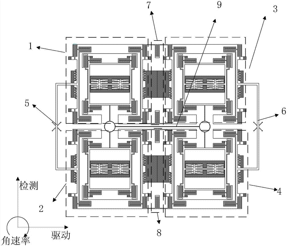
[0021] figure 1 It is a schematic diagram of the main structure of the four-mass micromechanical gyroscope directly coupled with the angular rate sensitive direction according to the embodiment of the present invention. like figure 1 As shown, the four-mass micromechanical gyroscope directly coupled to the angular rate sensitive direction of the present invention includes an upper left mass 1, a lower left mass 2, an upper right mass 3, a lower right mass 4, a left driving coupling beam 5, a right The side drives the coupling beam 6 , the center upper part drives the coupling beam 7 , and the center lower part drives the coupling beam 8 .

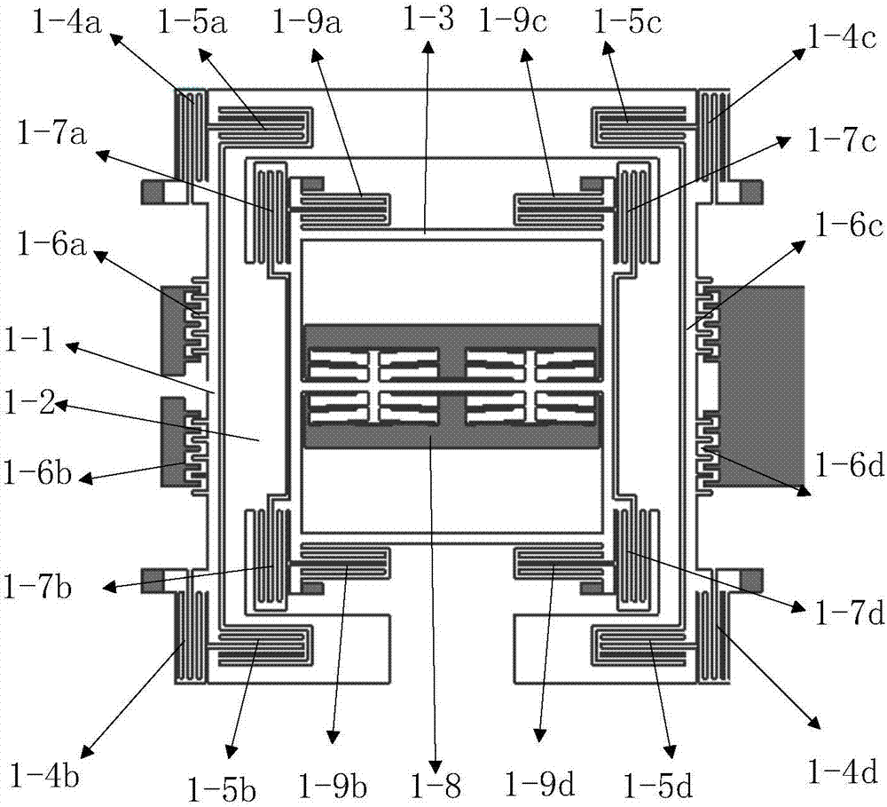
[0022] The structures of the four mass blocks are the same, and the structure of the upper left mass block is used for illustration...


PUM


Abstract

The invention belongs to the field of micromechanical gyroscopes and in particular relates to a four-mass block micromechanical gyroscope capable of being directly coupled in an angular rate sensitive direction. The four-mass block micromechanical gyroscope comprises four mass blocks of the same structure, two driving coupling beams on the outer side, two groups of central coupling beams and a detection coupling beam. Drive frames of the four mass blocks are connected by virtue of the two driving coupling beams on the outer side and the two groups of central coupling beams so as to realize direct coupling in the driving direction. Detection frames of the four mass blocks are connected by virtue of the detection coupling beam so as to realize direct coupling in the angular rate sensitive direction. The four-mass block micromechanical gyroscope structure is in a holohedral symmetry manner along the drive and detection directions. According to the four-mass block micromechanical gyroscope disclosed by the invention, an outside vibration signal can be decomposed into two components along the drive direction and the detection direction, while the output signal of the detection frame of the four mass blocks can eliminate the influences of the two components by virtue of a difference method, so that the influence of external vibration on the micromechanical gyroscope is eliminated.

Description

technical field [0001] The invention belongs to the field of micro-mechanical gyroscopes, in particular to a four-mass-block micro-mechanical gyroscope directly coupled with angular rate sensitive directions. Background technique [0002] The micromechanical gyroscope can sensitively measure the angular velocity of the carrier in the inertial space, and has the advantages of small size and easy mass production, so it is widely used in the fields of inertial navigation and guidance. Current research in this field mainly focuses on single-mass and dual-mass structures, with an emphasis on realizing the decoupling of the driving mode and detection mode motion of the micromechanical gyroscope. [0003] In order to further improve the performance of micro-machined gyroscopes, a small number of four-mass micro-machined gyroscopes have been proposed in recent years. The gyro units have realized the decoupling of the driving mode and the detection mode. A single-anchor four-mass ME...

Claims


Application Information

Patent Timeline
Patent Type & Authority Applications(China)
IPC IPC(8): G01C19/5656
CPCG01C19/5656
Inventor 王永王刚熊恒余才佳任伶
Owner XIAN FLIGHT SELF CONTROL INST OF AVIC
Why Eureka
Try Eureka