Heat sink

A technology of heat dissipation device and heat pipe, which is applied to electrical components, electric solid state devices, circuits, etc., can solve problems such as non-conformity with heat dissipation devices, and achieve the effects of improving thermal conductivity, improving heat dissipation efficiency, and increasing heat dissipation area.

Active Publication Date: 2017-10-24
AURAS TECH
View PDF4 Cites 3 Cited by
  • Summary
  • Abstract
  • Description
  • Claims
  • Application Information

AI Technical Summary

Problems solved by technology

[0002] With the improvement of the performance of electronic products, various heat dissipation structures or heat dissipation devices applied to electronic products are also flourishing. Among them, the existing common fin-type heat dissipation devices have fins that are mostly of the same specification and arranged neatly. The heat dissipation efficiency is still directly proportional to the heat dissipation area of ​​the fins, which no longer meets the strict standards that the current heat dissipation device is developing towards lightweight, but it is hoped that the heat dissipation efficiency can be further improved

Method used


Image

  • Heat sink
  • Heat sink
  • Heat sink

Examples


Embodiment Construction

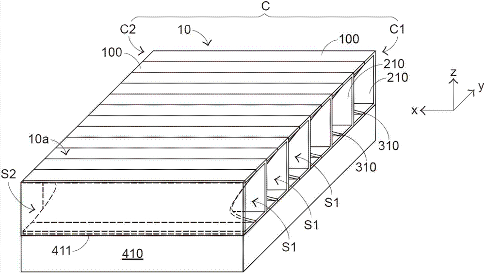
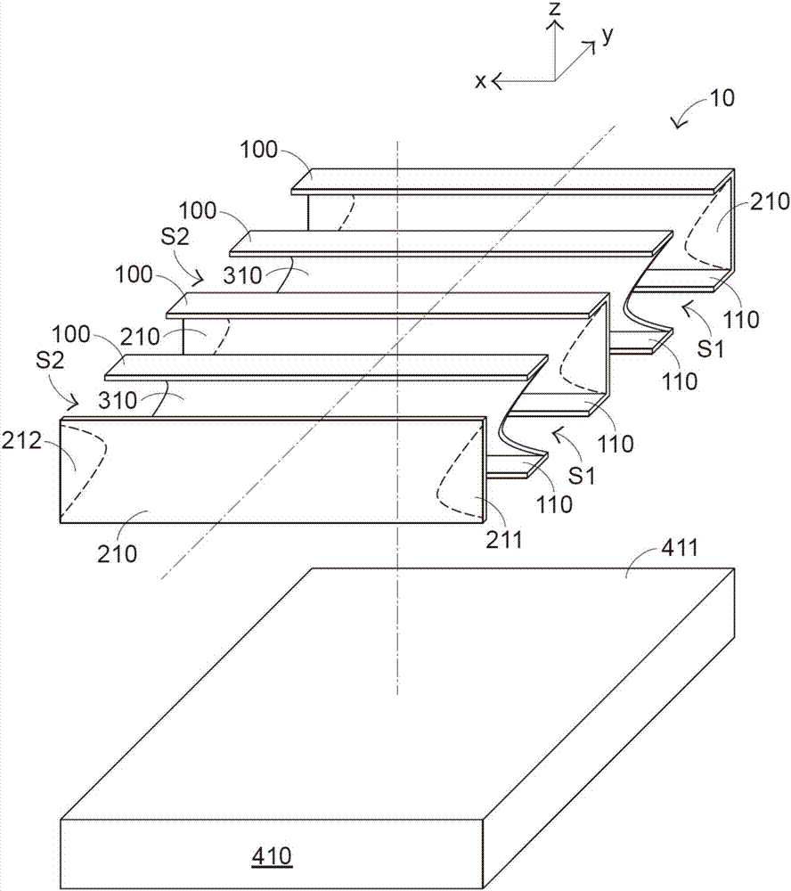
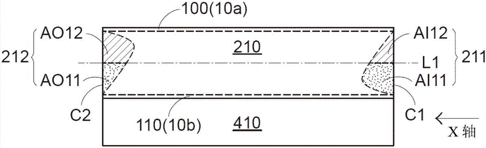
[0031] First of all, please refer to the three-axis directions shown in the figures of each embodiment, and define the X-axis direction as the front-to-back direction of the heat sink; the Y-axis direction is the left-right direction of the heat sink, which is the sequence of the fins described in the present invention. The axial direction of the radiator is composed of staggered intervals; the Z-axis direction is the up and down direction of the radiator. In the description of the present invention, the heating element is relatively arranged below the radiator for the convenience of explanation, but it is not limited thereto. .

[0032] see Figure 1A to Figure 1C , Figure 1A It is a three-dimensional schematic view of the first embodiment of the heat dissipation device of the present invention. Figure 1B for Figure 1A An exploded view of a partial implementation of the first embodiment of the heat sink shown. Figure 1C for Figure 1A In the heat dissipation device show...


PUM


Abstract

The invention provides a heat sink which is connected with a heating surface of a heating piece. The heat sink includes a bottom surface, a top surface, plural first fins and plural second fins. The plural first fins and the plural second fins are alternately and separately arranged between the top surface and the bottom surface along a specified axis direction. Moreover, plural airflow channels are defined by the plural first fins, the plural second fins, the top surface and the bottom surface collaboratively. The first fin has a first non-overlapped zone and a second non-overlapped zone with respect to a projection area of the second fin along the specified axis direction. The first non-overlapped zone is located at an airflow inlet. In the first non-overlapped zone, the lower portion is wider than the upper portion. The second non-overlapped zone is located at an airflow outlet. In the second non-overlapped zone, the upper portion is wider than the lower portion. The heat sink can improve heat radiating efficiency.

Description

technical field [0001] The present invention relates to a heat dissipation device, in particular to a fin type heat dissipation device. Background technique [0002] With the improvement of the performance of electronic products, various heat dissipation structures or heat dissipation devices applied to electronic products are also flourishing. Among them, the existing common fin type heat dissipation devices have fins that are mostly of the same specification and arranged neatly. The heat dissipation efficiency is still directly proportional to the heat dissipation area of ​​the fins, which does not meet the strict standards that the current heat dissipation device is developing toward lightweight but it is hoped that the heat dissipation efficiency can be further improved. [0003] Another kind of existing fin-type cooling device, such as the Chinese Taiwan New Patent Publication No. M270414 patent invented by the inventor of the present application, is to arrange two kind...

Claims


Application Information

Patent Timeline
Patent Type & Authority Applications(China)
IPC IPC(8): H01L23/367
CPCH01L23/367H05K7/20154H05K7/20336
Inventor 陈恒隆周建车
Owner AURAS TECH
Why Eureka
Try Eureka