Eureka AIR delivers breakthrough ideas for toughest innovation challenges, trusted by R&D personnel around the world.

High-strength and fireproof electrical cabinet

An electrical cabinet, high-strength technology, applied in the direction of fire rescue, substation/distribution device casing, etc., can solve the problems of explosion, increase the weight of the box, disadvantageous use, etc., to reduce manufacturing costs, improve explosion-proof performance, and easy to use. Effect

Active Publication Date: 2017-10-24
JIANGSU SHENYI ELECTRIC CO LTD
View PDF5 Cites 4 Cited by
  • Summary
  • Abstract
  • Description
  • Claims
  • Application Information

AI Technical Summary

Problems solved by technology

[0003] Because some components will be damaged if they are used or installed improperly, open flames or explosions will easily occur after damage, which puts forward greater requirements for the protection of electrical boxes. Sealing effect to improve protection performance, but it will increase the weight of the box, which is not conducive to use

Method used


Image

  • High-strength and fireproof electrical cabinet
  • High-strength and fireproof electrical cabinet
  • High-strength and fireproof electrical cabinet

Examples


Embodiment 1

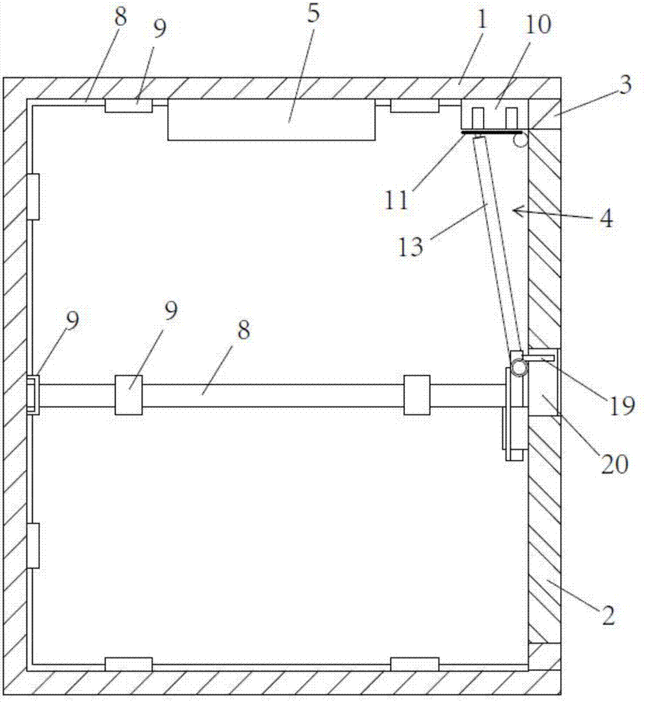
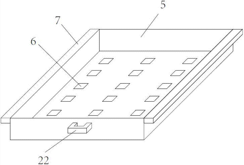
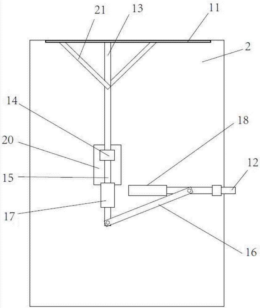
[0021] refer to figure 1 and figure 2 As shown, a high-strength fireproof electrical cabinet includes a cabinet 1 and a door 2, a door frame 3 is arranged on the cabinet, a door hinge and a lock body 4 are arranged between the door and the door frame, and the door rotates along the door hinge , to realize the switching effect, the lock body can ensure the locking effect of the box door, a fire extinguishing box 5 is arranged on the top inside of the cabinet, a number of powder drop holes 6 are opened on the bottom of the fire extinguishing box, and fire extinguishing powder is arranged in the fire extinguishing box, and the fire extinguishing powder passes through Hot-melt adhesive film covering setting, when there is an open flame, the hot-melt adhesive film will be melted, and the internal fire extinguishing powder will fall directly from the powder drop hole to realize fire extinguishing, and the hot-melt adhesive film will not ignite, avoiding secondary open flame.

[0...

Embodiment 2

[0028] The difference between Embodiment 2 and Embodiment 1 is that the magnetic base cooperates with the magnet to form a magnetic base, the magnet is connected to the rotating part, the rotating part is connected to the lock cylinder, the lock cylinder is set on the cabinet, and the rotation of the lock cylinder drives the rotation of the rotation part , the rotating part drives the magnet to rotate, and the magnetic switch effect of the magnetic base can be realized. When the magnetic force is turned on, the magnetic rotating plate can be sucked up to achieve the locking effect. When the magnetic force is turned off, the magnetic rotating plate cannot be sucked up. The effect of unlocking is realized by falling due to its own weight.


PUM


Abstract

The invention discloses a high-strength and fireproof electrical cabinet. The high-strength and fireproof electrical cabinet comprises a box cabinet and a box door, wherein a door frame is arranged on the box cabinet, a door hinge and a locking body are arranged between the box door and the door frame, a fire extinguishing box is arranged at a top part of an inner side of the box cabinet, a plurality of powder falling holes are formed in a bottom part of the fire extinguishing box, fire extinguishing powder is arranged in the fire extinguishing box and is wrapped by a hot melting membrane, guide convex blocks are arranged at two sides of the fire extinguishing box and are connected with guide sliding blocks in a matching way, the guide sliding blocks are fixedly connected with the box cabinet, a plurality of steel belts are arranged in the box cabinet along a horizontal direction and a vertical direction, two ends of the steel belts are welded and fixed with the corresponding door frame, a plurality of guide seats are also arranged between surfaces of the steel belts and an inner wall of the box cabinet, and punching parts are arranged on the guide seats. By the high-strength and fireproof electrical cabinet, fire can be timely extinguished when an open fire occurs in a component, and the box body is high in firmness.

Description

technical field [0001] The invention relates to the field of electric equipment, in particular to a high-strength fireproof electrical cabinet. Background technique [0002] The electrical box is a cabinet made of steel to protect the normal operation of components. The materials for making electrical cabinets are generally divided into two types: hot-rolled steel plates and cold-rolled steel plates. Electrical boxes are widely used mainly in chemical industry, environmental protection industry, power system, metallurgical system, industry, nuclear power industry, fire safety monitoring, transportation industry. [0003] Because some components will be damaged if they are used or installed improperly, open flames or explosions will easily occur after damage, which puts forward greater requirements for the protection of electrical boxes. The sealing effect is used to improve the protection performance, but it will increase the weight of the box, which is not conducive to us...

Claims


Application Information

Patent Timeline
Patent Type & Authority Applications(China)
IPC IPC(8): H02B1/28A62C3/16
CPCA62C3/16H02B1/28Y02A30/14
Inventor 杨成华
Owner JIANGSU SHENYI ELECTRIC CO LTD
Why Eureka
Eureka Blog
Learn More