
Current source grid-connecting converter control method

A converter control and current source technology, applied in the direction of converting AC power input to DC power output, AC network to reduce harmonics/ripples, electrical components, etc., can solve system control delay, control algorithm complexity, reduce system Stability margin and other issues, to achieve the effect of small control delay, realize grid side current, and reduce double frequency pulsation

Active Publication Date: 2017-10-24
河北申科电力股份有限公司 +5
View PDF4 Cites 3 Cited by
  • Summary
  • Abstract
  • Description
  • Claims
  • Application Information

AI Technical Summary

Problems solved by technology

However, such methods require the estimation of positive sequence components and negative sequence components, resulting in complex control algorithms, system control delays, and reduced system stability margins.

Method used


Image

  • Current source grid-connecting converter control method
  • Current source grid-connecting converter control method
  • Current source grid-connecting converter control method

Examples


Embodiment Construction

[0017] The specific implementation manners of the present invention will be described in further detail below in conjunction with the accompanying drawings.

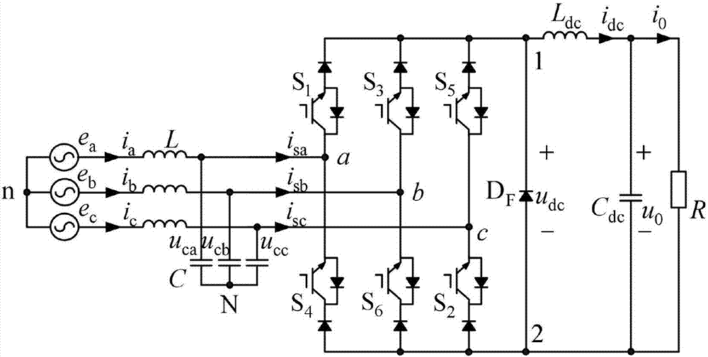
[0018] A control method of a current source grid-connected converter of the present invention, figure 1 Shown is the circuit schematic diagram of the current source grid-connected converter, figure 2 Shown is the schematic diagram of the control method of the current source grid-connected converter, and implementing the method of the present invention includes the following steps:

[0019] Step 1: Sampling the DC side output voltage u through the voltage Hall sensor o , with a given DC voltage reference value u o * The voltage error signal is obtained by subtraction, and then the DC current reference value i is obtained through the control of the first PI regulator dc * ;

[0020] Step 2: Sample the DC side output current i through the current Hall sensor dc , with the current reference value i dc * After the c...


PUM


Abstract

The invention discloses a current source grid-connecting converter control method, comprising: subtracting a given DC voltage reference value from a sampled DC side outputted voltage to obtain a voltage error signal; via the control of a first PI regulator, obtaining a DC current reference value; comparing the sampled DC side outputted current with a current reference value to obtain a current error signal controlled by a second PI regulator, wherein the DC side outputted current is controlled by the feedback resonance; subtracting the two outputs to obtain a modulation signal amplitude; using the phase angle theta of the sampled grid voltage and the detected grid voltage; multiplying the modulation signal amplitude by the orthogonal unit signals sin theta and -cos theta to obtain the modulation signals M[alpha] and M[beta] in a two-phase stationary coordinate system; using a notch filter to filter the third harmonic wave in the modulation signals M[alpha] and M[beta] to obtain new modulation signals M[alpha] and M[beta]; then respectively calculating the amplitude m and the phase angle information; and through the space vector modulation method, generating the driving signals. The method of the invention can effectively reduce the double frequency pulsation at the direct current output side and realize the sine wave of the network side current at the same time.

Description

technical field [0001] The invention belongs to a control method for a current source grid-connected converter, in particular to a control method for a current source grid-connected converter under the condition of unbalanced grid voltage. Background technique [0002] In recent years, power electronic devices have continued to expand in the industrial market and application fields. Three-phase grid-connected converters, as grid-side converters, can achieve unity power factor operation, reduce grid-side current distortion, and realize energy feedback. Compared with the voltage source grid-connected converter, the current source grid-connected converter has unique advantages. For example, the output voltage can be adjusted upwards from zero, there is no risk of bridge arm through-through, and the reliability is high. It is used in photovoltaic power generation systems, wind power systems, multi- It has been applied in fields such as electric aircraft power supply system and m...

Claims


Application Information

Patent Timeline
Patent Type & Authority Applications(China)
IPC IPC(8): H02J3/46H02J3/26H02J3/01H02M7/00
CPCH02J3/01H02J3/26H02J3/46H02M7/00Y02E40/40Y02E40/50
Inventor 郭小强张雪
Owner 河北申科电力股份有限公司
Learn More