Grinding direction control instrument for oral cavity

A direction control instrument and oral technology, applied in the field of medical devices, can solve the problems of time-consuming and labor-intensive, low degree of intelligence, unable to meet the needs of use, etc., and achieve the effect of convenient use, high degree of intelligence, and strong adaptability

Active Publication Date: 2017-10-27
鲁旭飞
View PDF3 Cites 2 Cited by
  • Summary
  • Abstract
  • Description
  • Claims
  • Application Information

AI Technical Summary

Problems solved by technology

[0002] In the prior art: the patent application publication number of CN 102626346A discloses an oral grinding direction control instrument, which includes a retainer in the mouth, on which a variable joint is arranged, and the inner ball of the variable joint is connected with a universal ball to change the direction. There is a fixed screw at the lower end of the joint, the first parallel rod is connected to the upper end of the universal ball, and the first swing rod is connected to the rotation on the first parallel rod. The first swing rod and the second swing rod are connected by a rotating shaft, and the second swing rod Hinged with the sleeve, there is a second parallel rod inside the sleeve, the lower end of the second parallel rod is provided with an angle adjustment static plate, which is provided with a first groove and a second groove, and an angle adjustment movable plate is equipped with the angle adjustment static plate. The angle adjustment disk is provided with a protrusion, and the angle adjustment disk is also provided with an adjustment column, which is connected with a button, and an openable fixed ring is arranged at the lower end of the angle adjustment disk, and the fixed ring There is also a buckle on the top, which adopts a manual adjustment method, which is time-consuming and laborious, and has a low degree of intelligence, which cannot meet the needs of use

Method used


Image

  • Grinding direction control instrument for oral cavity
  • Grinding direction control instrument for oral cavity
  • Grinding direction control instrument for oral cavity

Examples


Embodiment Construction

[0014] The following will clearly and completely describe the technical solutions in the embodiments of the present invention with reference to the accompanying drawings in the embodiments of the present invention. Obviously, the described embodiments are only some, not all, embodiments of the present invention. Based on the embodiments of the present invention, all other embodiments obtained by persons of ordinary skill in the art without making creative efforts belong to the protection scope of the present invention.

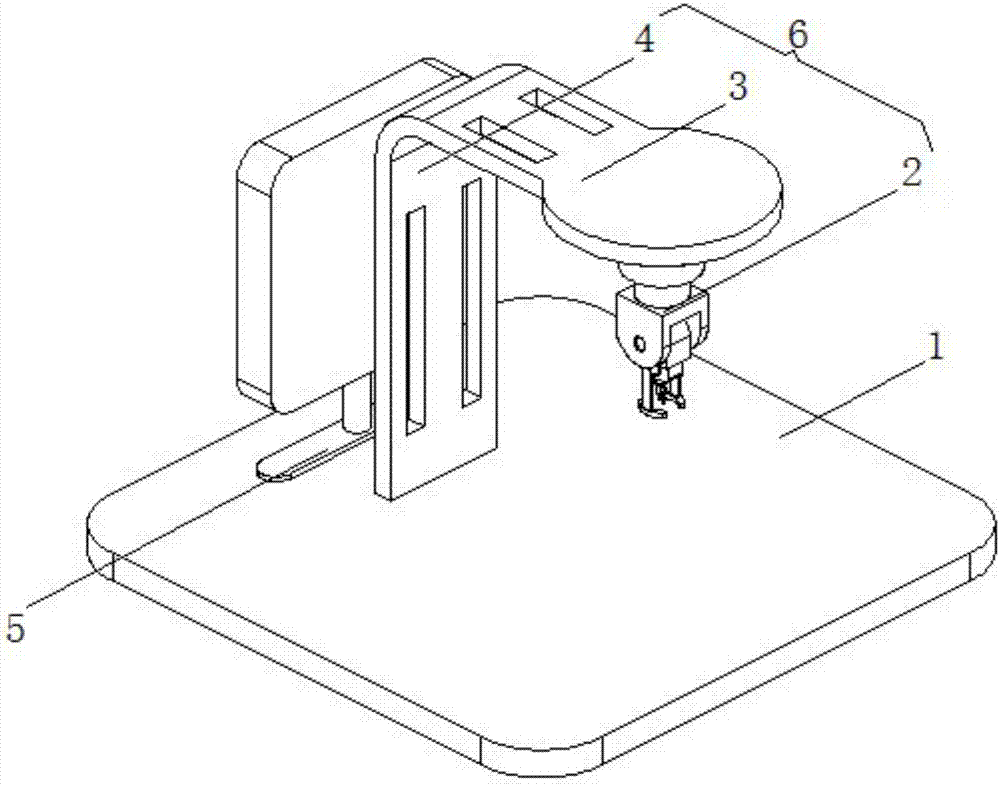
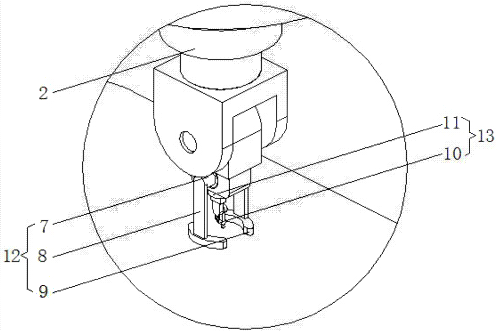
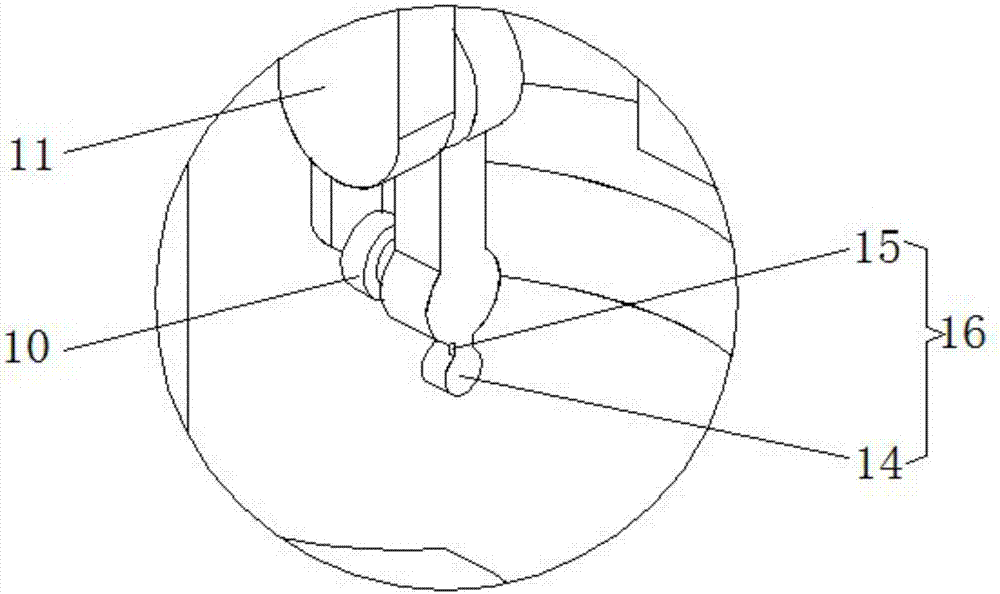
[0015] see Figure 1-3 , the present invention provides a technical solution: an oral grinding direction control instrument, including a workbench 1, an open-source single-chip microcomputer 5 and an adjustment mechanism 6 are respectively installed on the top of the workbench 1, and the left and right sides of the end of the adjustment mechanism 6 are symmetrically installed with Oral cavity fixing device 12, the end of adjusting mechanism 6 is equipped with ...


PUM


Abstract

The invention discloses a grinding direction control instrument for an oral cavity. The grinding direction control instrument comprises a working table, wherein an open source singlechip and an adjusting mechanism are respectively mounted at the top of the working table; oral cavity fixing devices are symmetrically mounted on the left side and the right side of the end part of the adjusting mechanism; a grinding direction control device is mounted at the end part of the adjusting mechanism. According to the grinding direction control instrument for the oral cavity, the working positions of the oral cavity fixing devices and the grinding direction control device are adjusted by the adjusting mechanism, so that the grinding direction control instrument is simple to operate and convenient to use, and convenience is provided for the work of medical staffs; the oral cavity of a patient is fixed by the oral cavity fixing devices with an adjusting capacity, so that the grinding direction control instrument is strong in adaptability and can be used for different patients, and using requirements can be met; the surgical direction is adjusted by the grinding direction control device with high degree of freedom, so that the grinding direction control instrument is high in intelligence and is time-saving and labor-saving; therefore, the working intensity of the medical staffs is greatly relieved; a surgical vision is provided for the medical staffs by a monitoring device, so that surgical operations of the medical staffs are facilitated.

Description

technical field [0001] The invention relates to the technical field of medical devices, in particular to an oral grinding direction control instrument. Background technique [0002] In the prior art: the patent application publication number of CN 102626346A discloses an oral grinding direction control instrument, which includes a retainer in the mouth, on which a variable joint is arranged, and the inner ball of the variable joint is connected with a universal ball to change the direction. There is a fixed screw at the lower end of the joint, the first parallel rod is connected to the upper end of the universal ball, and the first swing rod is connected to the rotation on the first parallel rod. The first swing rod and the second swing rod are connected by a rotating shaft, and the second swing rod Hinged with the sleeve, there is a second parallel rod inside the sleeve, the lower end of the second parallel rod is provided with an angle adjustment static plate, which is pro...

Claims


Application Information

Patent Timeline
Patent Type & Authority Applications(China)
IPC IPC(8): A61C3/06A61C19/00
CPCA61C3/06A61C19/00A61C2204/00
Inventor 鲁旭飞毕宝泉于茂辉
Owner 鲁旭飞
Why Eureka
Try Eureka