
Supercharged centrifugal casting device for motor rotor

A motor rotor and centrifugal casting technology, which is applied in the field of casting equipment, can solve problems such as easy noise, poor exhaust, and product performance degradation, and achieve the effects of ensuring shape and dimension accuracy, improving production efficiency, and improving casting quality

Active Publication Date: 2019-01-01
WOLONG ELECTRIC GRP CO LTD
View PDF9 Cites 0 Cited by
  • Summary
  • Abstract
  • Description
  • Claims
  • Application Information

AI Technical Summary

Problems solved by technology

[0003] The gap between the guide bar and the iron core of the squirrel cage rotor formed by the centrifugal casting process is large, which is easy to generate noise. At the same time, the cast aluminum quality and size of the upper aluminum ring are not easy to control, and the scrap is serious.
The gap between the squirrel cage rotor guide bar and the iron core and the size of the aluminum ring are easy to ensure by die casting technology, but due to the rapid molding under high pressure, the exhaust is not smooth, and large pores are prone to appear in the aluminum ring, which leads to product performance. decline

Method used


Image

  • Supercharged centrifugal casting device for motor rotor
  • Supercharged centrifugal casting device for motor rotor
  • Supercharged centrifugal casting device for motor rotor

Examples


Embodiment Construction

[0058] The technical solutions of the embodiments of the present invention will be explained and described below in conjunction with the accompanying drawings of the embodiments of the present invention, but the following embodiments are only preferred embodiments of the present invention, not all of them. Based on the examples in the implementation manners, other examples obtained by those skilled in the art without making creative efforts all belong to the protection scope of the present invention.

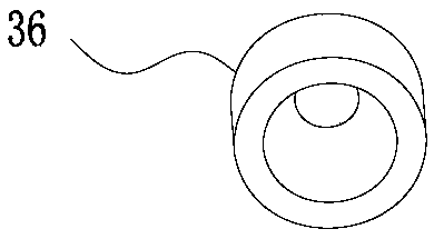
[0059] Such as Figure 1 to Figure 21 As shown, the motor rotor pressurized centrifugal casting device of the embodiment of the present invention includes:

[0060] The upper mold 1, the lower mold 2 and the rotor core 8 constituting the mold cavity;

[0061] The mold opening and closing mechanism 4 for lifting the lower mold 2, the mold opening and closing mechanism 4 is arranged below the lower mold 2, and it includes a mold clamping cylinder 41 and a mold clamping ejector pi...


PUM


Abstract

The invention belongs to the technical field of casting equipment, and particularly relates to a motor rotor pressure increasing type centrifugal pouring device. Aiming at the insufficiency that since a centrifugal pouring or pressure casting technology is adopted in an existing motor mouse cage rotor, the size and the air exhaust are difficult to consider simultaneously. According to the technical scheme, the motor rotor pressure increasing type centrifugal pouring device comprises an upper mold, a lower mold, a rotor iron core, an open-close mold mechanism used for ascending and descending the lower mold, a rotation mechanism for driving the upper mold and the lower mold which have a linkage relation to rotate, a feed cylinder with a metal liquid accommodation cavity, a feed inlet pipe provided with a feed inlet and a pressure increasing mechanism which presses metal liquid used for forming a rotor into a mold cavity, wherein the upper mold, the lower mold and the rotor iron core constitute a mold cavity;, the pressure increasing mechanism is arranged above the upper mold, and comprises a pressure increasing cylinder and a press rod driven by the pressure increasing cylinder, and the press rod is rotatably inserted into the feed inlet pipe and the feed cylinder. The motor rotor pressure increasing type centrifugal pouring device is provided with the rotation mechanism and the pressure increasing mechanism simultaneously, the air exhaust and the size are guaranteed, and the casting quality is improved.

Description

technical field [0001] The invention belongs to the technical field of casting equipment, and in particular relates to a motor rotor pressurized centrifugal casting device and a casting method. Background technique [0002] For a long time, there are generally two processes for aluminum casting of motor squirrel cage rotors: centrifugal casting and pressure casting. Centrifugal casting, that is, when the rotor core is rotating, the molten metal is poured into the gate, and it is formed under the action of the molten metal's own weight and centrifugal force. Die casting, that is, the molten molten metal enters the mold cavity and rotor core groove under pressure, and is formed under pressure. For the existing centrifugal casting machine, please refer to the Chinese utility model patent whose authorized announcement number is CN 201621268563 U and the name is a kind of fully automatic centrifugal casting machine for cast aluminum rotor. [0003] The gap between the guide bar...

Claims


Application Information

Patent Timeline
Patent Type & Authority Patents(China)
IPC IPC(8): B22D13/10B22D27/09
CPCB22D13/10B22D27/09
Inventor 王斌陈永根
Owner WOLONG ELECTRIC GRP CO LTD
Learn More