Simple inclined core pulling device for injection mold

An injection mold and oblique core-pulling technology, which is applied in the field of injection mold oblique extraction and demolding devices, can solve the problems of many faulty nodes, complex structure and high manufacturing cost, and achieve the effects of reducing operating failures, wide adaptability and cost reduction.

Inactive Publication Date: 2017-10-27
NINGBO RUIYUAN MOLD & PLASTICS
View PDF4 Cites 4 Cited by
  • Summary
  • Abstract
  • Description
  • Claims
  • Application Information

AI Technical Summary

Problems solved by technology

[0003] For the core-pulling and demoulding of the oblique structure inside the product, the existing technology uses the oil cylinder to drive the core rod and the oblique core-pulling block through the oblique slider to carry out oblique pulling and demoulding. Figure 4 , because the work of the oil cylinder involves the hydraulic source, oil circuit, and control, the structure of the auxiliary mechanism of the inclined slider of the oil cylinder is complex, there are many links, and there are many potential failure nodes, the failure rate is high, the reliability is poor, and the operation and maintenance costs are high. In addition, the inclined slider of the oil cylinder The auxiliary mechanism occupies a large internal space of the mold, resulting in a large mold shape and high manufacturing costs; therefore, the existing technology has the problems and deficiencies of complex structure, poor reliability, and high cost

Method used


Image

  • Simple inclined core pulling device for injection mold
  • Simple inclined core pulling device for injection mold
  • Simple inclined core pulling device for injection mold

Examples


Embodiment Construction

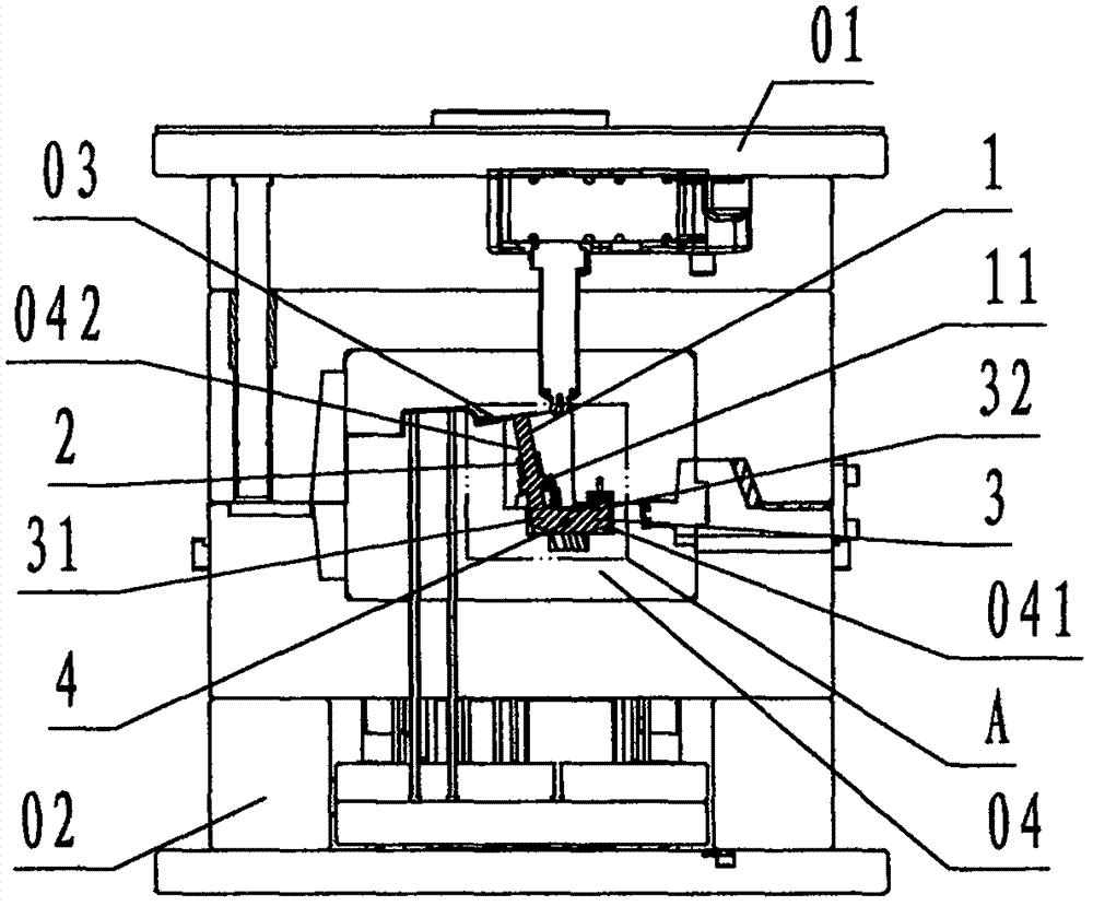
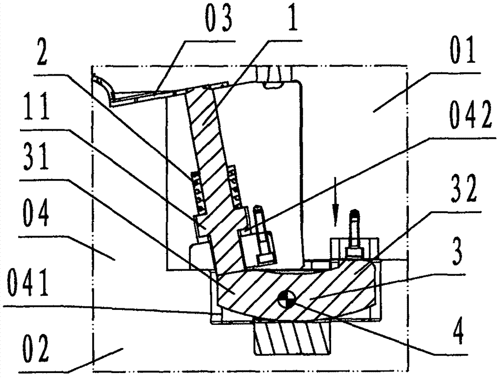
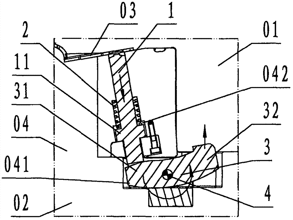
[0024] refer to Figure 1 ~ Figure 3 , a simple oblique core-pulling device for an injection mold of the present invention, comprising an oblique core-pulling 1, a spring 2, a skid 3, and a rotating shaft 4, wherein: the oblique core-pulling 1 is a cylindrical step-shaped steel member, and the oblique core-pulling The upper end of 1 is provided with the profile of the molded product 03, and the lower cylindrical surface of the oblique core-pulling 1 is provided with a flange called a stopper 11;

[0025] The spring 2 is a cylindrical helical compression spring;

[0026] The skid block 3 is a steel member with upturned left and right ends and an arc-shaped block. The middle part of the skid block 3 is provided with a circular through hole in the front and rear direction called the shaft hole, and the skid block 3 is located in the shaft hole. The left part of the shaft hole is called the resistance arm 31, and the right part of the skid block 3 located in the shaft hole is cal...


PUM


Abstract

The invention discloses a simple inclined core pulling device for an injection mold. The simple inclined core pulling device comprises an inclined pulling core (1), a spring (2), a skid (3) and a rotating shaft (4), wherein the inclined pulling core adopted in the invention is a cylindrical stepped steel member provided with a profile surface and a blocking platform; the skid is an arc block-shaped steel member having two upwarped ends; a shaft hole is formed in the skid; a left part of the skid is a resistance arm; a right part of the skid is a power arm; a skid groove for mounting the skid and an inclined pulling guide hole are formed in a mold core of the mold; the skid is rotatably arranged in the skid groove through the shaft hole and the rotating shaft; the inclined pulling core is located in the inclined pulling guide hole in a sliding manner; the spring is located in the inclined pulling guide hole; a lower end of the inclined pulling core is in contact with the resistance arm of the skid; the power arm of the skid is in contact with a fixed mold. A technical scheme that the spring works, the skid is rotated anticlockwise and the inclined pulling core is separated from a product when the mold is opened, and the fixed mold forces the power arm to reset, the skid is rotated clockwise and the inclined pulling core is reset when the mold is closed is adopted, so that the injection mold achieves the purposes of simplifying a structure, working reliably and reducing costs.

Description

technical field [0001] The invention relates to an injection mold oblique pulling and demoulding device, in particular to a simple oblique core pulling device for an injection mold used for oblique core-pulling and demoulding for an oblique structure inside a product. Background technique [0002] Explanation: The core-pulling and demoulding of injection molds can be divided into longitudinal, transverse and oblique directions. The so-called longitudinal direction is along the opening and closing direction of the injection mold, the so-called transverse direction is the direction orthogonal to the longitudinal direction, and the so-called oblique direction is between the longitudinal direction and the transverse direction. direction between. The side of the injection molded product used to connect to other objects is called the inner side or inner side, and the side opposite to the inner side is called the outer side or outer side. [0003] For the core-pulling and demouldi...

Claims


Application Information

Patent Timeline
Patent Type & Authority Applications(China)
IPC IPC(8): B29C45/33
CPCB29C45/33
Inventor 华宏伟葛军川王荣余
Owner NINGBO RUIYUAN MOLD & PLASTICS
Why Eureka
Try Eureka