Protective device of displacement sensor and belt self-moving machine tail with displacement sensor

A technology of displacement sensor and protective device, applied in the direction of conveyor control device, conveyor, conveyor objects, etc., can solve the problems of high cost, difficult maintenance and replacement, high precision requirements, and achieve the effect of avoiding influence

Pending Publication Date: 2017-10-27
NINGXIA TIANDI BENNIU IND GRP
View PDF14 Cites 0 Cited by
  • Summary
  • Abstract
  • Description
  • Claims
  • Application Information

AI Technical Summary

Problems solved by technology

At present, the commonly used magnetostrictive displacement sensor is usually installed inside the oil cylinder, which requires high precision, is difficult to maintain and replace, is expensive, and is not easy to popularize.
The use of external displacement sensors can not only reduce costs, but also facilitate maintenance and replacement. However, external sensors need to consider the protection and installation of sensors.

Method used


Image

  • Protective device of displacement sensor and belt self-moving machine tail with displacement sensor
  • Protective device of displacement sensor and belt self-moving machine tail with displacement sensor
  • Protective device of displacement sensor and belt self-moving machine tail with displacement sensor

Examples


Embodiment Construction

[0023] In order to more clearly illustrate the technical solutions of the embodiments of the present invention, the following will briefly introduce the accompanying drawings that need to be used in the embodiments. Obviously, the accompanying drawings in the following description are some embodiments of the present invention. Ordinary technicians can also obtain other drawings based on these drawings on the premise of not paying creative work.

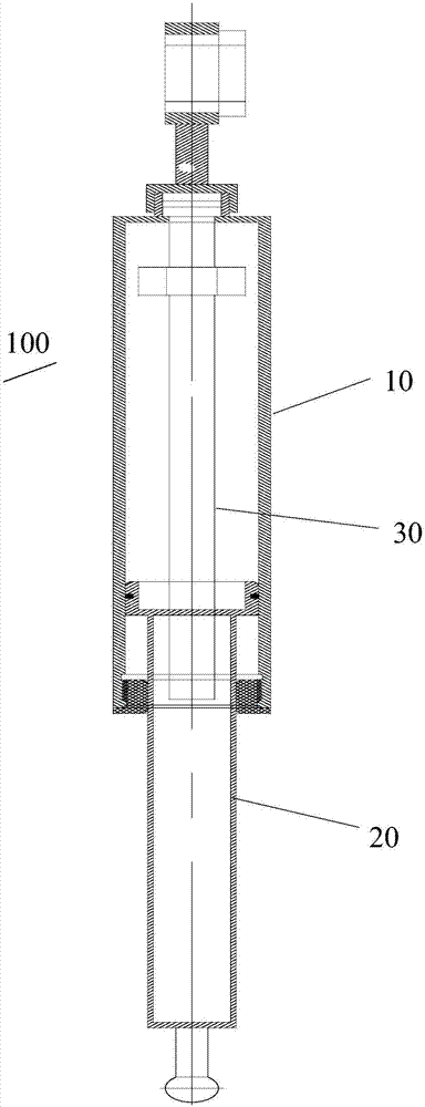
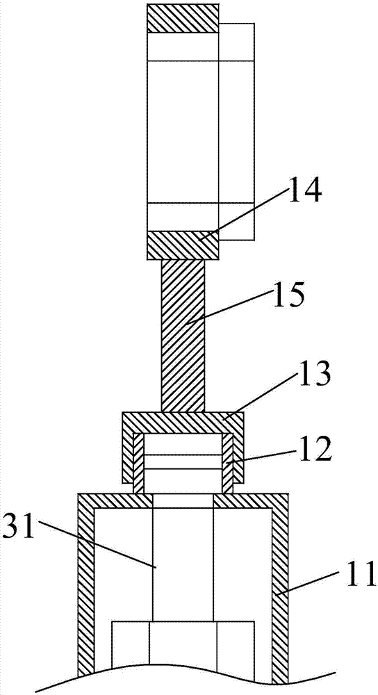
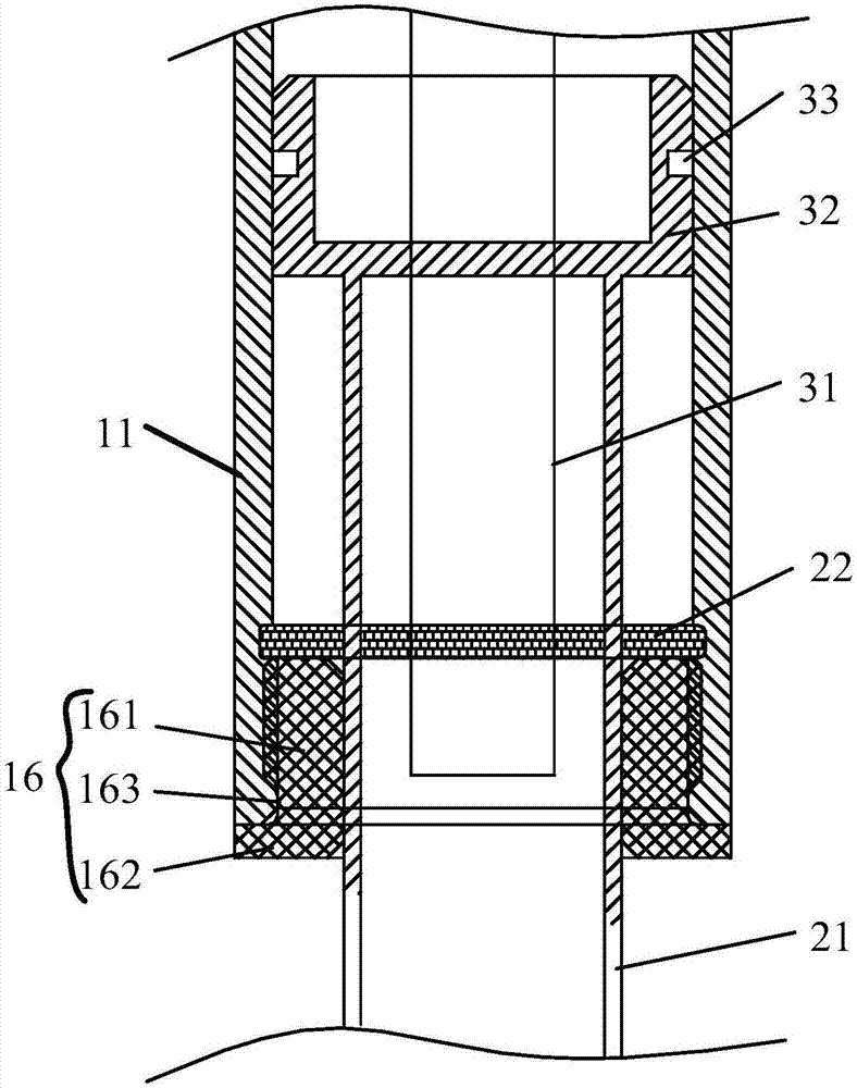
[0024] see Figure 1 to Figure 4 , the embodiment of the present invention provides a displacement sensor protection device 100, including a fixed assembly 10, a sliding assembly 20, a displacement sensor 30, the fixed assembly 10 has a closed cavity for placing the displacement sensor 30, and the sliding assembly 20 is sealed in the fixed assembly 10 The bottom opening of the closed cavity of the fixed assembly 10, and the displacement sensor 30 in the fixed assembly 10 is connected with the sliding assembly 20, so that the displacem...


PUM


Abstract

Disclosed is a protective device of a displacement sensor. The protective device comprises a fixed assembly, a sliding assembly and the displacement sensor; the fixed assembly is provided with a closed cavity for placing the displacement sensor; the opening in the bottom of the closed cavity of the fixed assembly is blocked by the sliding assembly, and the displacement sensor in the fixed assembly is connected with the sliding assembly, so that the sliding assembly drives the displacement sensor to slide up and down in the closed cavity of the fixed assembly, and displacement measurement is achieved. The protective device of the displacement sensor is fixed between a cylinder barrel of a leveling oil cylinder and a piston rod of the leveling oil cylinder by the fixed assembly and the sliding assembly, and the displacement sensor is arranged inside the fixed assembly and the sliding assembly, so that the displacement sensor is installed in a closed mode and prevented from being influenced by external environment, and meanwhile the synchronous movement and measurement of the displacement sensor and the piston rod of the leveling oil cylinder are achieved.

Description

technical field [0001] The invention relates to the technical field of automatic control of a belt self-moving tail, in particular to a displacement sensor protection device and a belt self-moving tail provided with a displacement sensor. Background technique [0002] The belt self-moving machine tail is the transport equipment along the trough of the fully mechanized mining face. It connects the bridge loader and the belt conveyor along the trough. The machine is a fulcrum for each other, realizing the self-moving action of stepping, and at the same time, it can correct the deviation between the machine body and the center line of the belt, and realize the function of belt leveling and deviation adjustment. However, the existing belt self-moving machine tails are all manually operated, requiring operators to observe with the naked eye and manually adjust the expansion and contraction of the leveling cylinder to realize the leveling function of the belt. [0003] In order t...

Claims


Application Information

Patent Timeline
IPC IPC(8): B65G21/00B65G15/30B65G43/02
CPCB65G15/30B65G21/00B65G43/02B65G2203/0266B65G2203/042
Inventor 李洋朱秀梅董海宁王继国卜侃侃刘庆华王进军
Owner NINGXIA TIANDI BENNIU IND GRP
Why Eureka
Try Eureka