Compressor

A technology for compressors and compressing fluids, applied in the field of compressors, can solve problems such as the decrease of static pressure efficiency and supercharging efficiency, and achieve the effect of improving supercharging efficiency

Active Publication Date: 2017-10-31
HONDA MOTOR CO LTD
View PDF6 Cites 4 Cited by
  • Summary
  • Abstract
  • Description
  • Claims
  • Application Information

AI Technical Summary

Problems solved by technology

Therefore, the static pressure efficiency at the outlet of the compressor impeller decreases, resulting in a problem that the boosting efficiency decreases

Method used


Image

  • Compressor
  • Compressor
  • Compressor

Examples


Embodiment Construction

[0053] An embodiment of the present invention will be described below with reference to the drawings.

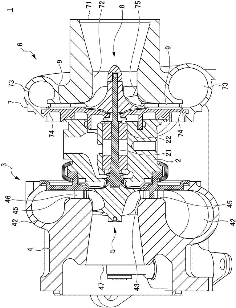
[0054] figure 1 It is a sectional view showing the structure of the supercharger 1 to which the compressor of this embodiment is applied.

[0055] The supercharger 1 has a bearing housing 2 , a turbine 3 assembled on one end side of the bearing housing 2 , and a compressor 6 assembled on the other end side of the bearing housing 2 . The bearing housing 2 has a rod-shaped rotating shaft 21 extending between the turbine 3 and the compressor 6 , and a bearing 22 that rotatably supports the rotating shaft 21 .

[0056] The turbine 3 has: a turbine casing 4 constituting a part of an exhaust passage of an internal combustion engine (not shown); and a turbine impeller 5 provided in the turbine casing 4 .

[0057]The turbine casing 4 is provided with: a tubular exhaust intake portion 41 connected to the exhaust pipe of the internal combustion engine; an annular swirl passage 42 th...


PUM


Abstract

The present invention provides a compressor capable of suppressing vibration and fluid separation of blades of a compressor impeller and improving supercharging efficiency. The impeller of the compressor has: a conical wheel; and a plurality of plate-shaped main blades and splitters extending along the shroud on the outer peripheral surface of the wheel from the front edge portion as the intake inlet to the rear edge portion as the intake outlet. blade. The angle distribution of the distal end edges of the main blades and the splitter blades facing the shroud is convex upward from the respective leading edge portions to the trailing edge portions. In addition, the cross-sectional shape of the trailing edge portion of these main blades and the splitter blades is an arc shape.

Description

technical field [0001] This invention relates to compressors for compressing fluids. Background technique [0002] Conventionally, if a fixed diffuser is arranged downstream of a compressor that compresses intake air flowing through an intake passage of an internal combustion engine, when the air compressed by the compressor wheel passes through the fixed diffuser, a nozzle wake (pressure change). Then, the upstream compressor impeller is subjected to the excitation force caused by the wake of the nozzle, whereby a phenomenon in which the blades of the compressor impeller vibrate occurs. [0003] On the other hand, from the viewpoint of securing blade strength against blade vibration, it is conceivable to form the blade shape of the compressor impeller so that the cross-sectional thickness of the blade is thick. However, there is a trade-off relationship between the strength of the blades of the compressor impeller and the aerodynamic performance, and there is a limit to s...

Claims


Application Information

Patent Timeline
Patent Type & Authority Applications(China)
IPC IPC(8): F04D29/30F04D29/66
CPCF04D29/30F04D29/284F04D29/666
Inventor 伊藤直纪小穴峰保久野直树
Owner HONDA MOTOR CO LTD
Why Eureka
Try Eureka