
Dust collection device

A technology of dust removal device and dust removal tower, which is applied in the direction of combination device, gas treatment, membrane technology, etc., can solve the problems of ineffective treatment of waste gas, and achieve the effect of avoiding water and controlling air quality

Inactive Publication Date: 2017-11-03
湖南锐取环保科技有限公司
View PDF3 Cites 0 Cited by
  • Summary
  • Abstract
  • Description
  • Claims
  • Application Information

AI Technical Summary

Problems solved by technology

[0003] The invention provides a dust removal device to solve the technical problem that the device in the prior art cannot effectively treat the waste gas generated in the production process

Method used


Image

  • Dust collection device
  • Dust collection device

Examples


Embodiment Construction

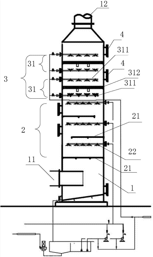
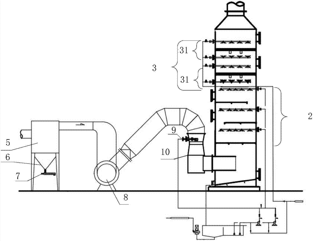
[0019] The implementation of the present invention will be described in detail below in conjunction with the accompanying drawings and examples, so that implementers of the present invention can fully understand how the present invention uses technical means to solve technical problems, and achieve the realization process of technical effects and according to the above-mentioned realization process The present invention is implemented concretely. It should be noted that, as long as there is no conflict, each embodiment and each feature in each embodiment of the present invention can be combined with each other, and the formed technical solutions are all within the protection scope of the present invention.

[0020] figure 1 It is a schematic structural diagram of a dust removal device provided by an embodiment of the present invention. like figure 1 As shown, this embodiment provides a dust removal device, including: a dust removal tower 1, and a first dust removal layer 2 f...


PUM

PropertyMeasurementUnit
diameteraaaaaaaaaa

Abstract

The invention provides a dust collection device. The dust collection device comprises a dust collection tower, a first dust collection layer and a second dust collection layer, wherein the first dust collection layer is arranged in the dust collection tower and is used for removing dust particles and sulfur dioxide; the second dust collection layer is used for absorbing water drops; an inlet is formed in one end of the dust collection tower; an outlet is formed in the other end of the dust collection tower; and waste gas enters the dust collection tower through the inlet, successively passes through the first dust collection layer and the second dust collection layer, and then is discharged via the outlet. The dust particles and the sulfur dioxide are removed by the first dust collection layer, the water drops are absorbed by the second dust collection layer, water droplets in the waste gas can be removed thoroughly, therefore, clean and dry gas is obtained, the circumstance that the waste gas contains water is avoided, and the air quality of a surrounding environment is controlled effectively.

Description

technical field [0001] The invention relates to the technical field of environmental protection, in particular to a dust removal device. Background technique [0002] With the development of power electronics industry technology, the production of various industries is also speeding up rapidly, so it is imperative to improve the technological level of products, product quality, production output and efficiency. However, while focusing on improving the technological level, quality, output, and efficiency of products, the issue of industrial waste gas emissions is often overlooked. For example, in the process of producing enameled wire, due to the use of a large amount of organic solvents and cured substances (polyester paint, polyester imide, etc.), after many high-temperature curing processes of dipping paint, a large amount of organic matter volatilizes and a small amount of The high-temperature waste gas produced by the high-temperature pyrolysis of the cured product has ...

Claims


Application Information

Patent Timeline
Patent Type & Authority Applications(China)
IPC IPC(8): B01D50/00B01D53/04B01D53/14B01D53/18B01D53/26
CPCB01D53/04B01D53/1481B01D53/18B01D53/26B01D2258/02B01D2253/102B01D50/10
Inventor 刘军袁珺李国林
Owner 湖南锐取环保科技有限公司
Learn More