Metal part locating grab bucket

A technology of metal parts and mechanical grippers, applied in the field of parts positioning and clamping, can solve the problems of waste, not easy to find, lost and so on

Inactive Publication Date: 2017-11-03
聂文斌
View PDF5 Cites 4 Cited by
  • Summary
  • Abstract
  • Description
  • Claims
  • Application Information

AI Technical Summary

Problems solved by technology

[0003] In order to solve the above problems, the present invention provides a positioning grab for metal parts, which can solve the problem that the parts are relatively small and will be lost if you don’t pay attention, and it is not easy to find after the loss, which will easily cause waste.

Method used


Image

  • Metal part locating grab bucket
  • Metal part locating grab bucket

Examples


Embodiment Construction

[0016] In order to make the technical means, creative features, goals and effects achieved by the present invention easy to understand, the present invention will be further described below in conjunction with specific illustrations.

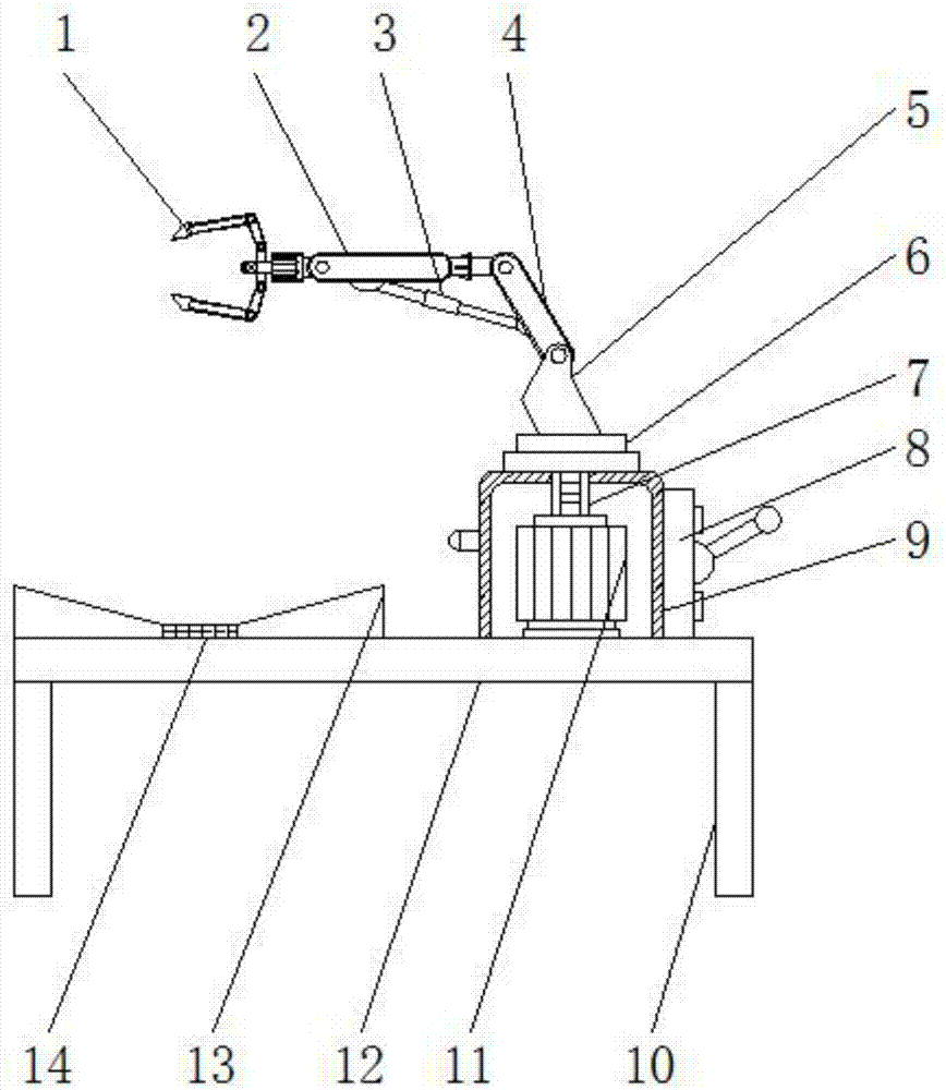
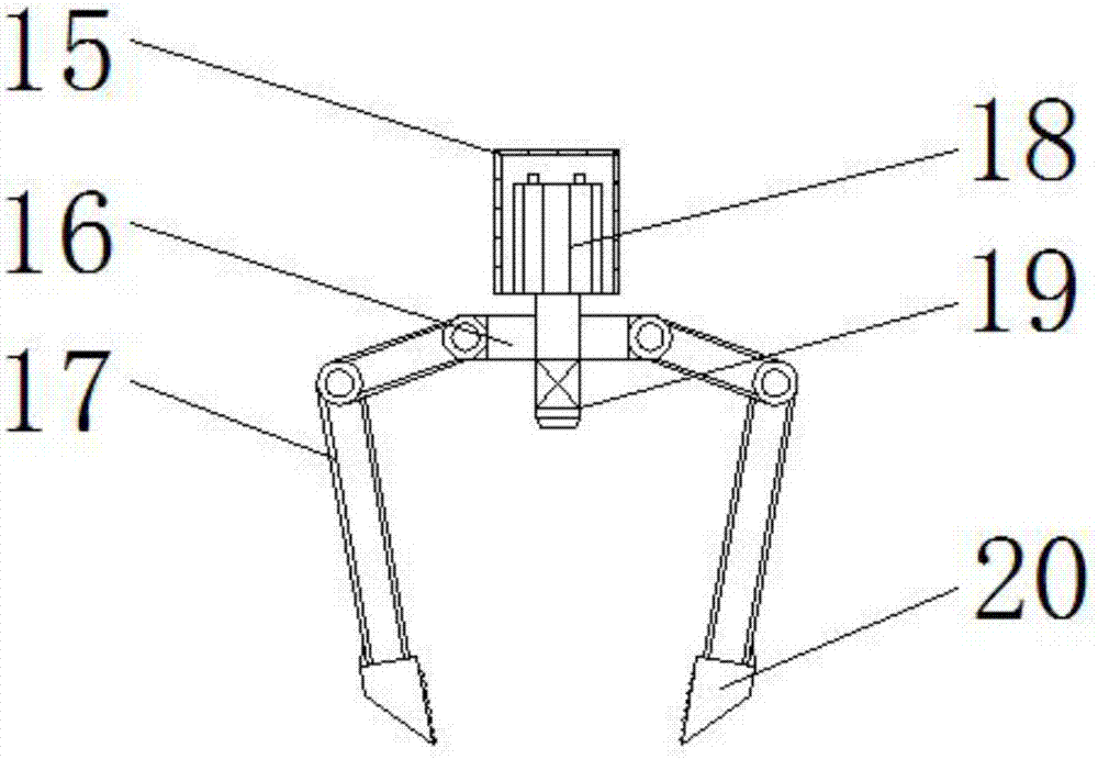
[0017] Such as Figure 1 to Figure 2 As shown, a metal parts positioning grab includes a mechanical gripper 1, a control box 8, a first motor 11, a support plate 12, an infrared receiver 14 and a second motor 18, and the four corners at the bottom of the support plate 12 are installed Support column 10 is arranged, and receiving platform 13 is installed on one side of supporting plate 12 tops, and the section of receiving platform 13 is concave shape, and the central position place of receiving platform 13 is equipped with infrared receiver 14, and the top of infrared receiver 14 is installed with Transparent protective partition, the other side of support plate 12 tops is equipped with the first motor box 9, and the first motor box 9 is away fr...


PUM


Abstract

The invention relates to a metal part positioning grab, which includes a mechanical gripper, a control box, a first motor, a support plate, an infrared receiver and a second motor. The four corners at the bottom of the support plate are all equipped with support columns. A receiving station is installed on one side of the top of the support plate, and an infrared receiver is installed at the central position of the receiving station, and a first motor box is installed on the other side of the top of the support plate, and the first electric box is far away from the receiving station. A control box is installed on one side, a first motor is installed inside the first motor box, and a rotating disk is installed on the top of the first motor through a rotating shaft. The present invention is equipped with a second motor, a connecting platform, a gripper and a non-slip rubber sleeve, and when gripping a part, the gripper is adjusted according to the size of the part, so that the gripper is more convenient and fast, and the gripper does not need to be replaced. Hand-sized, can pick up any size parts.

Description

technical field [0001] The invention relates to the technical field of parts positioning and clamping, in particular to a metal parts positioning grab. Background technique [0002] With the continuous development of society and the continuous advancement of science, various electronic products continue to emerge. At present, in the assembly of machinery, some small parts are usually used, such as screws, washers, pins and other small parts for assembly. Since the number of small parts needed is determined during assembly, the operator usually selects by category when selecting, and the number of different specifications is different. Such selection will waste a lot of time and increase the assembly of the entire machine. Time, in order to avoid prolonging the assembly time, operators usually take more small parts than required to facilitate assembly. However, due to the relatively small parts, they will be lost if they are not noticed, and they will not be recovered after t...

Claims


Application Information

Patent Timeline
Patent Type & Authority Applications(China)
IPC IPC(8): B23P19/00B23P21/00
CPCB23P19/007B23P21/00
Inventor 聂文斌孔凡黎贤志
Owner 聂文斌
Why Eureka
Try Eureka