A plywood hot-press setting device

A setting device and technology for plywood, applied in the field of sheet metal processing, can solve the problems of low production efficiency, long time-consuming plywood, inability to move heavy objects, etc., and achieve the effect of reducing operation steps and improving work efficiency

Active Publication Date: 2019-05-07
徐州春艺阳木业有限公司
View PDF7 Cites 0 Cited by
  • Summary
  • Abstract
  • Description
  • Claims
  • Application Information

AI Technical Summary

Problems solved by technology

[0002] Plywood is one of the commonly used materials for furniture. It is one of the three major boards of wood-based panels. It can also be used for aircraft, ships, trains, automobiles, buildings and packaging boxes. It is a three-layer or multi-layer board-like material that is sliced ​​into thin wood and then glued with an adhesive. The plywood needs to be pressed during the processing to achieve the purpose of shaping. Traditionally, the operation of this processing step is through heavy objects. Pressing, however, because heavy objects cannot move during pressing, the corners of the plywood cannot be stressed, resulting in secondary processing. At the same time, the plywood takes a long time in the process of pressing and shaping, resulting in low production efficiency

Method used


Image

  • A plywood hot-press setting device
  • A plywood hot-press setting device
  • A plywood hot-press setting device

Examples


Embodiment Construction

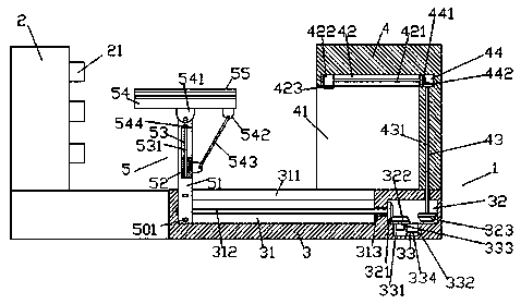
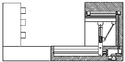
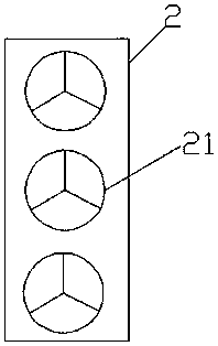
[0019] Such as figure 1 and image 3 As shown, a plywood hot-press setting device of the present invention includes a frame body 3, a heating part 2 is provided on the upper left side of the frame body 3, and a plurality of sets of heating parts are provided on the upper and lower side faces of the heating part 2. device 21, the heater 21 is used to heat the pressed plywood, the upper right side of the frame body 3 is provided with a pressing part 4, and all the parts between the pressing part 4 and the heating part 2 The frame body 3 is provided with a regulating part 5, and the inside of the right side of the frame body 3 is provided with a first sliding groove 31, and the top of the first sliding groove 31 is provided with a The first transmission groove 32 is provided in the frame body 3 on the right side of the first sliding groove 31, and the first screw extending to the left and right sides is arranged in the first sliding groove 31. Shaped rod 312, the extension sect...


PUM


Abstract

The invention discloses a plywood hot-pressing sizing device. The plywood hot-pressing sizing device comprises a frame body, a heating part is arranged on the upper portion of the left side of the frame body, multiple heaters are arranged on the end face of the right side of the heating part in an up-and-down manner, a pressure exerting part is arranged on the upper portion of the right side of the frame body, and an adjusting and control part is arranged on the portion, between the pressure exerting part and the heating part, of the frame body; a first sliding groove is formed inside the right side of the frame body, the top of the first sliding groove is provided with an empty groove which is formed in an extending manner along the first sliding groove, and a first transmission groove is formed in the portion, at the right side of the first sliding groove, in the frame body; a first spiral rod which extends towards the left side and the right side is arranged in the first sliding groove, the right side extending section of the first spiral rod penetrates through the inner wall of the frame body and is rotationally connected with the inner wall of the frame body in a matched manner, and the tail of the right side of the first spiral rod penetrates into the first transmission groove and is provided with a first toothed connection wheel; the bottom of the first transmission groove is provided with a second sliding groove, a second spiral rod is arranged in the second sliding groove, the tail of the right side of the second spiral rod is connected with a first electric motor, and a first sliding block is connected to the second spiral rod in a threaded and matched manner; and a second electric motor is arranged in the top of the first sliding block, and the top of the second electric motor is provided with a main tooth connection wheel which penetrates into the first transmission groove and is rotationally connected with the first transmission groove in a matched manner.

Description

technical field [0001] The invention relates to the technical field of plate processing, in particular to a plywood hot-press setting device. Background technique [0002] Plywood is one of the commonly used materials for furniture. It is one of the three major boards of wood-based panels. It can also be used for aircraft, ships, trains, automobiles, buildings and packaging boxes. It is a three-layer or multi-layer board-like material that is sliced ​​into thin wood and then glued with an adhesive. The plywood needs to be pressed during the processing to achieve the purpose of shaping. Traditionally, the operation of this processing step is through heavy objects. Pressing, however, because heavy objects cannot move during pressing, the corners of the plywood cannot be stressed, resulting in secondary processing. At the same time, the plywood takes a long time in the process of pressing and shaping, resulting in low production efficiency. Contents of the invention [0003]...

Claims


Application Information

Patent Timeline
Patent Type & Authority Patents(China)
IPC IPC(8): B27D3/00
CPCB27D3/00
Inventor 官鸿运
Owner 徐州春艺阳木业有限公司
Why Eureka
Try Eureka