Concrete stirring device for construction site

A mixing device and construction site technology, which is applied in the direction of cement mixing device, clay preparation device, mixing operation control device, etc., can solve problems such as difficulty in feeding materials, poor concrete quality, and troublesome operation of workers, so as to improve mixing quality and reduce processing costs. Noise, the effect of improving stirring efficiency

Inactive Publication Date: 2017-11-03
童贤波
View PDF0 Cites 7 Cited by
  • Summary
  • Abstract
  • Description
  • Claims
  • Application Information

AI Technical Summary

Problems solved by technology

At present, the domestic large-scale concrete mixing equipment first directly mixes sand, gravel, water, cement and additives according to the proportion, and then mixes them through the mixing equipment at one time. However, the internal mixing mechanism of this equipment is Rotate evenly, so that the materials are stirred regularly, resulting in a long mixing period of the materials, and the sand or stones are not stirred or are not stirred evenly, which leads to poor quality of the produced concrete and cannot achieve satisfactory results, and large concrete The mixing equipment is tall and difficult to feed materials, which brings great troubles to the workers' operation

Method used


Image

  • Concrete stirring device for construction site
  • Concrete stirring device for construction site
  • Concrete stirring device for construction site

Examples


Embodiment Construction

[0018] The technical solution of this patent will be further described in detail below in conjunction with specific embodiments.

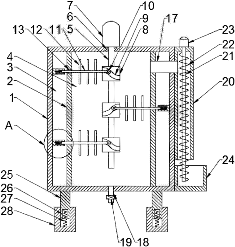
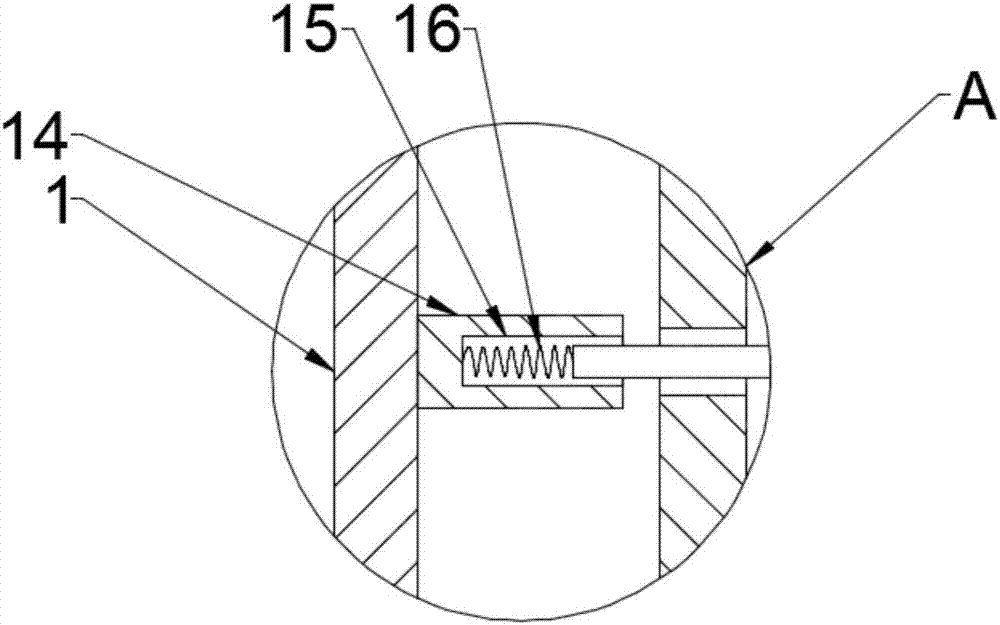
[0019] see Figure 1~3 , a concrete mixing device for a construction site, comprising a cabinet 1, the inner cavity of the cabinet 1 is symmetrically provided with partitions 2, and the partition 2 is provided with a plurality of through holes 13, and the partition 2 divides the interior of the cabinet 1 The cavity is divided into a stirring cavity 4 and two clamping cavities 3, and the two clamping cavities 3 are symmetrically arranged on the left and right sides of the stirring cavity 4, and the inner wall of one side of the clamping cavity 3 is provided with a number of holes corresponding to the through holes 13. The top cover 14, the top cover 14 and the through hole 13 are in a one-to-one relationship, the top cover 14 is provided with a top hole 15, the stirring chamber 4 is provided with a main stirring rod 5, and the main stirring rod 5 T...


PUM


Abstract

The invention discloses a concrete mixing device for a construction site, which comprises a machine case. The inner chamber of the machine case is symmetrically provided with partitions, and a plurality of through holes are arranged on the partition board. The partition board divides the inner chamber of the machine case into a mixing chamber and two The inner wall of the clamping chamber is provided with a number of top sleeves corresponding to the through holes. The top sleeve is provided with a top hole. The stirring chamber is equipped with a main stirring rod. The top of the main stirring rod passes through the chassis and is fixedly connected. On the motor shaft of the main motor, a number of rotating rollers are evenly arranged on the main stirring rod. Track grooves are arranged on the rotating rollers, and rollers are arranged in the track grooves. The auxiliary stirring rods are fixedly connected to the rollers. There are several stirring blades, and the bottom of the cabinet is evenly provided with several legs; the main motor of the present invention drives the main stirring rod to rotate, and then drives the rotating roller to rotate, and the rotating roller drives the auxiliary stirring rod to stir, so that the stirring blades stir irregularly Materials, improve the mixing efficiency of materials, and ensure that sand or stones are completely stirred.

Description

technical field [0001] The invention relates to the technical field of concrete mixing, in particular to a concrete mixing device for a construction site. Background technique [0002] Concrete, referred to as "concrete" for short: refers to the collective name of engineering composite materials in which aggregates are cemented into a whole by cementitious materials. Generally speaking, the term concrete refers to the cement concrete obtained by using cement as the cementitious material, sand and stone as the aggregate; mixed with water (may contain admixtures and admixtures) in a certain proportion, and stirred. Concrete, which is widely used in civil engineering. [0003] The mixing of concrete usually requires the use of concrete mixing equipment. At present, the domestic large-scale concrete mixing equipment first directly mixes sand, gravel, water, cement and additives according to the proportion, and then mixes them through the mixing equipment at one time. However, ...

Claims


Application Information

Patent Timeline
Patent Type & Authority Applications(China)
IPC IPC(8): B28C5/14B28C5/16B28C7/14
CPCB28C5/147B28C5/0806B28C5/0856B28C5/16B28C7/14
Inventor 童贤波
Owner 童贤波
Why Eureka
Try Eureka