Lifting tool for grounding wire flat iron of concrete pole for power transmission line

A technology for power transmission lines and grounding wires, which is applied to lifting devices, crowbars, etc. It can solve the problems that it is not convenient for the grounding flat iron to cling to the concrete pole, the bolts cannot be directly fixed to the hole, and the hand block is heavy and heavy, so as to achieve the lifting operation Stability, high safety and stability, shortened working time

Pending Publication Date: 2017-11-03
ZHUMADIAN POWER SUPPLY ELECTRIC POWER OFHENAN +1
5 Cites 0 Cited by

AI-Extracted Technical Summary

Problems solved by technology

[0002] Accurate measurement of grounding resistance can verify whether the design of the grounding system is reasonable, detect changes or defects in the grounding system in time, and avoid economic losses or accidents that may be caused by unqualified grounding. Usually, we use a grounding shaker to measure grounding resistance. During the process, the grounding wire needs to be removed from the concrete pole, but after dismantling, it is difficult to fix the grounding wire on the concrete pole after the measurement. After the grounding resistance measurement, the bolt cannot be fixed directly because the ...

Abstract

The invention discloses a lifting tool for grounding wire flat iron of a concrete pole for a power transmission line. The lifting tool for the grounding wire flat iron of the concrete pole for the power transmission line comprises a support, a pry bar and a pry bar force-bearing component. The support comprises a long pole bolt, round steel and a base plate. One end of the round steel is welded to the base plate, the other end of the round steel is connected with one end of the long pole bolt, and the other end of the long pole bolt is connected with the pry bar force-bearing component. A nut is arranged on the joint of the long pole bolt and the round steel. The pry bar force-bearing component is connected with the pry bar. 45#steel is adopted to serve as the round steel. An internal thread is arranged in the round steel, and the dimension of the internal thread is matched with the size of an external thread on the long pole bolt. The long pole bolt is connected with the round steel through the external thread and the internal thread. The length of the pry bar can be adjusted. An anti-slip sleeve is arranged on the handhold portion of the pry bar, and a U-shaped frame with a certain width and a certain thickness is designed on the portion, making contact with the pry bar force-bearing component, of the pry bar. The lifting tool for the grounding wire flat iron of the concrete pole for the power transmission line is easy and convenient to operate and high in safety.

Application Domain

Crowbars

Technology Topic

Structural engineeringMechanical engineering +2

Image

  • Lifting tool for grounding wire flat iron of concrete pole for power transmission line
  • Lifting tool for grounding wire flat iron of concrete pole for power transmission line

Examples

  • Experimental program(1)

Example Embodiment

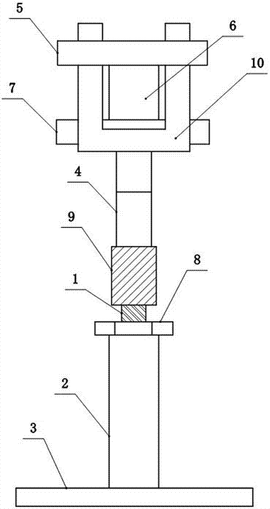
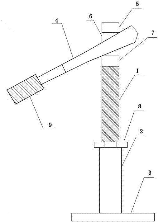
[0023] Embodiment: A flat iron lifting tool for the concrete pole grounding wire of a transmission line, including a bracket, a crowbar 4 and a crowbar bearing member. The bracket includes a long rod bolt 1, a round steel 2 and a bottom plate 3. One end of the round steel 2 is welded to On the bottom plate 3, the other end is connected with one end of the long rod bolt 1, the other end of the long rod bolt 1 is connected with the crowbar bearing part, the connection between the long rod bolt 1 and the round steel 2 is provided with a nut 8, the crowbar bearing part Connect with crowbar 4.
[0024] Round steel 2 is made of 45# steel. Round steel 2 is provided with internal threads. The size of the internal thread matches the external thread on long rod bolt 1. Long rod bolt 1 and round steel 2 are connected by external and internal threads.
[0025] The crowbar 4 is a length-adjustable crowbar 4, the gripping part of the crowbar 4 is provided with a non-slip sleeve 9, and the contact part with the crowbar bearing member is designed as a U-shaped frame 10 with a certain width and thickness.
[0026] The load-bearing components of the crowbar include the anti-stripping steel block 5, the connecting rod 6 and the crowbar washer steel block 7. One end of the connecting rod 6 is connected with the long rod bolt 1, and the other end passes through the crowbar pad steel 7 and then connects to the anti-stripping steel block 7. Block 5 connection.
[0027] The bottom plate 3 is a steel bottom plate 3 with a certain size.
[0028] When working, adjust the height of the bracket according to the actual situation, use the anti-dropping steel block 5 to withstand the ground wire flat iron, and then insert one end of the crowbar 4U-shaped frame 10 between the anti-dropping steel block 5 and the crowbar pad steel block 7. , The two side frames of the U-shaped frame 10 are respectively located on both sides of the connecting rod 6, hold the grip of the crowbar 4, and press the crowbar 4 downward. Use the principle of lever to push the flat steel of the ground wire to a predetermined position, and align the hole on the ground flat iron with the hole on the concrete rod. After alignment, insert the bolt into the hole of the concrete rod, and finally tighten the bolt with a wrench. .

PUM

no PUM

Description & Claims & Application Information

We can also present the details of the Description, Claims and Application information to help users get a comprehensive understanding of the technical details of the patent, such as background art, summary of invention, brief description of drawings, description of embodiments, and other original content. On the other hand, users can also determine the specific scope of protection of the technology through the list of claims; as well as understand the changes in the life cycle of the technology with the presentation of the patent timeline. Login to view more.

Similar technology patents

Graphene film and preparation method therefor

Owner:CHANGZHOU FUXI TECH CO LTD

Driving working load calculation method of automobile driver

InactiveCN101690666AImprove accuracy and timelinessEasy to operate
Owner:BEIJING UNIV OF TECH

Classification and recommendation of technical efficacy words

  • easy to operate
  • Improve stability and security

Lancet device

InactiveUS7303573B2inexpensively mass-producedeasy to operate
Owner:ABBOTT DIABETES CARE INC

Rapid and non-invasive optical detection of internal bleeding

InactiveUS20050065436A1easy to operaterapid and accurate result
Owner:HO WINSTON ZONH +2

Principal-subordinate integrated type surgical operation robot system

ActiveCN104013471Aavoid communication delaysImprove stability and security
Owner:SUZHOU KANGDUO ROBOT

Electric vehicle charging device

ActiveCN107139763AImprove stability and securityReduce electric shock accidents
Owner:JIANGSU XIYI HIGH NEW DISTRICT TECH DEV CO LTD

Control system for LEDs applied to plant illumination

InactiveCN102144508AImprove stability and security
Owner:WUHU VALEO AUTOMOTIVE LIGHTING SYST
Why Eureka
Try Eureka