A distribution cabinet

A power distribution cabinet and cabinet technology, applied in the field of electric power, can solve the problems affecting the performance and life of electrical components, unable to meet the needs of use, hidden dangers of safe operation of equipment, etc., to achieve repeatable adjustment, reduce personnel labor, and simple structure. Effect

Active Publication Date: 2019-01-25
遵化市福洋液压机械有限公司
View PDF4 Cites 0 Cited by
  • Summary
  • Abstract
  • Description
  • Claims
  • Application Information

AI Technical Summary

Problems solved by technology

Because the power distribution cabinet needs to be used in various environments, and because there are many important electrical components placed in the power distribution cabinet, affected by the change of ambient temperature, it is hot in summer and cold in winter, and it is very easy to be affected by moisture, which affects the safety of the equipment. The operation brings serious hidden dangers, which will affect the performance and life of electrical components, and cause damage to the power distribution cabinet. However, the power distribution cabinets in the prior art are mostly independent structures, and the temperature control method is mainly through the air conditioner in the machine room. The temperature capacity is poor, especially when there are many power distribution cabinets in a single computer room, it cannot meet the needs of use

Method used


Image

  • A distribution cabinet
  • A distribution cabinet
  • A distribution cabinet

Examples


Embodiment Construction

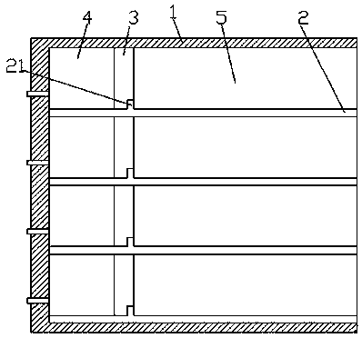
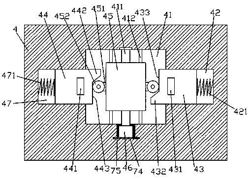
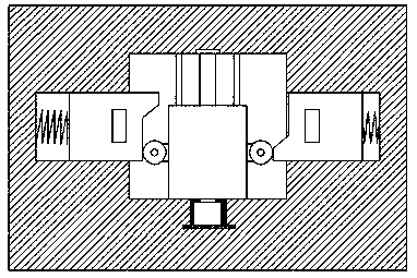
[0020] Such as Figure 1-Figure 7 As shown, a power distribution cabinet of the present invention includes a cabinet body 1, and multiple groups of equidistantly arranged partitions 2 are arranged in the cabinet body 1, and an adjustment device 4 is provided above each partition board 2 And the drawer assembly 5 connected by sliding fit, the air circulation area 3 is provided between the adjustment device 4 and the drawer assembly 5, and the front air duct 12 and the rear air intake duct 11 are provided on the left side of the adjustment device 4 , the adjusting device 4 is provided with a control chamber 41, the two sides of the control chamber 41 are symmetrically provided with a first chute 47 and a second chute 42, and the left and right side walls of the first chute 47 are symmetrically provided with The forward air hole 472 connected with the forward air pipe 12, the left and right side walls of the second chute 42 are symmetrically provided with the rear air inlet hole ...


PUM


Abstract

The invention discloses a safe power distribution cabinet. The safe power distribution cabinet comprises a cabinet body, wherein the cabinet body is internally provided with a plurality of partition boards arranged in an equally-spaced manner; an adjusting device and a drawer component connected with the adjusting device in sliding fit are arranged above each partition board; an air ventilation area is arranged between each adjusting device and the corresponding drawer component; a front air inlet pipe and a rear air inlet pipe which are arranged front and back are arranged on the left side of each adjusting device; each adjusting device is internally provided with a control cavity; a first sliding chute and a second sliding chute are symmetrically arranged on two sides of each control cabinet; front air inlet holes communicating with the front air inlet pipe are symmetrically formed in the left side wall and the right side wall of each first sliding chute; rear air inlet holes communicating with the rear air inlet pipe are symmetrically formed in the left side wall and the right side wall of each second sliding chute; each first sliding chute is internally in sliding joint with a first sliding block; each second sliding chute is internally in sliding joint with a second sliding block; a first through hole connected with the corresponding front air inlet holes in a matched manner is formed in the corresponding first sliding block; and a second through hole connected with the corresponding rear air inlet holes in the matched manner is formed in the corresponding second sliding block.

Description

technical field [0001] The invention relates to the field of electric power technology, in particular to a power distribution cabinet. Background technique [0002] Distribution cabinet, a box in which voltage appliances are placed. Collectively referred to as the power distribution center. They are centrally installed in the substation of the enterprise, and distribute the electric energy to the lower-level power distribution equipment in different locations. Because the power distribution cabinet needs to be used in various environments, and because there are many important electrical components placed in the power distribution cabinet, affected by the change of ambient temperature, it is hot in summer and cold in winter, and it is very easy to be affected by moisture, which affects the safety of the equipment. The operation brings serious hidden dangers, which will affect the performance and life of electrical components, and cause damage to the power distribution cabin...

Claims


Application Information

Patent Timeline
Patent Type & Authority Patents(China)
IPC IPC(8): H02B1/56
CPCH02B1/565
Inventor 任薇薇
Owner 遵化市福洋液压机械有限公司
Why Eureka
Try Eureka