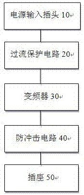
Intelligent power supply system
A power supply system and intelligent technology, applied in the field of power supply, can solve the problems of complex circuit, poor circuit stability, inability to perform frequency conversion, etc., and achieve the effect of simple circuit structure and low cost
- Summary
- Abstract
- Description
- Claims
- Application Information
AI Technical Summary
Problems solved by technology
Method used
Image

Examples
Embodiment Construction
[0014] In order to facilitate the understanding of the present invention, the present invention will be described more fully below with reference to the associated drawings. A preferred embodiment of the invention is shown in the drawings. However, the present invention can be embodied in many different forms and is not limited to the embodiments described herein. Rather, these embodiments are provided so that the disclosure of the present invention will be thorough and complete.
[0015] It should be noted that when a component is said to be "fixed" to another component, it can be directly on the other component or there can also be an intervening component. When a component is said to be "connected" to another component, it may be directly connected to the other component or there may be intervening components at the same time. The terms "vertical," "horizontal," "left," "right," and similar expressions are used herein for purposes of illustration only.
[0016] Unless ot...
PUM
 Abstract
Description
Claims
Application Information