
Data transmission method and wireless camera device

A wireless camera and data transmission technology, applied in wireless communications, closed-circuit television systems, electrical components, etc., can solve the problems of poor user experience, limited signal coverage, loss of monitoring images, etc., to achieve the effect of improving user experience

Inactive Publication Date: 2017-11-03
SHENZHEN SUNDRAY NETWORK SCI TECH
View PDF7 Cites 2 Cited by
  • Summary
  • Abstract
  • Description
  • Claims
  • Application Information

AI Technical Summary

Problems solved by technology

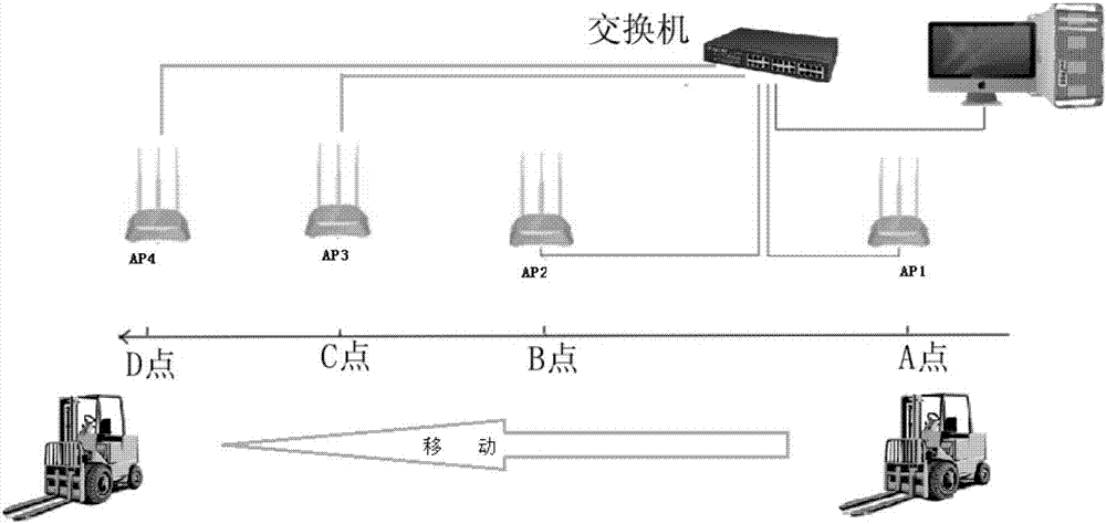
[0004] But for a network camera installed on a moving object (such as a sightseeing cable car, a forklift in a warehouse, a crane on a construction site, etc.), because a network camera using a wired network will be limited by the network cable, it is not suitable for installation on moving objects. Even if it is a wireless network camera using Wi-Fi, because the signal coverage of a wireless access point (English full name: Access Point, English abbreviation: AP) is limited, the network camera can only move within a small range. Because as long as it leaves the signal coverage of the connected AP, the digital video stream transmitted to the monitoring center will be interrupted, even if it quickly connects to another wireless AP, when it roams between the two APs, the video The stream will also be temporarily interrupted, resulting in the loss of monitoring images for a period of time when the monitoring center browses the monitoring video, resulting in a bad user experience

Method used


Image

  • Data transmission method and wireless camera device
  • Data transmission method and wireless camera device
  • Data transmission method and wireless camera device

Examples


Embodiment Construction

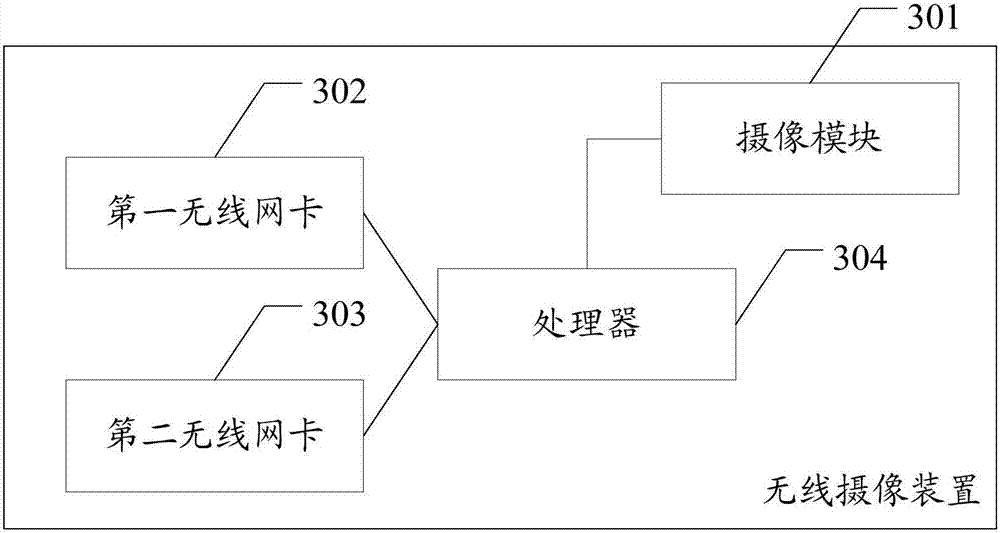
[0021] The embodiment of the present invention provides a data transmission method and a wireless camera device, which ensures that the image data received by the wireless receiving end will not be lost or interrupted during the movement of the wireless camera device, thereby improving user experience .

[0022] In order to enable those skilled in the art to better understand the solutions of the present invention, the following will clearly and completely describe the technical solutions in the embodiments of the present invention in conjunction with the drawings in the embodiments of the present invention. Obviously, the described embodiments are only It is an embodiment of a part of the present invention, but not all embodiments. Based on the embodiments of the present invention, all other embodiments obtained by persons of ordinary skill in the art without making creative efforts shall fall within the protection scope of the present invention.

[0023] The terms "first", ...


PUM


Abstract

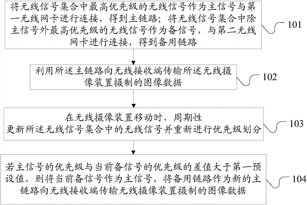
Embodiments of the invention disclose a data transmission method and a wireless camera device. The method comprises the steps of connecting a master signal in a wireless signal set with a first wireless network interface card, so as to obtain a main link; taking a wireless signal with highest priority in the wireless signal set except the master signal as a standby signal and connecting the standby signal with a second wireless network interface card so as to obtain a standby link; and when the wireless camera device moves, updating wireless signals in the wireless signal set periodically and re-prioritizing the wireless signals, and if a difference between the priority of the master signal and the priority of the current standby signal reaches a first preset value, using the standby link as a new main link to transmit data of images taken by the wireless camera device to a wireless receiving terminal. When the wireless camera device moves, it is ensured that image data received by the wireless receiving terminal is not lost or interrupted, so that the user experience is improved.

Description

technical field [0001] The invention relates to the technical field of video monitoring, in particular to a data transmission method and a wireless camera device. Background technique [0002] As Internet technology is becoming more and more popular in people's work and life, the combination of Internet technology and surveillance cameras has produced a new generation of surveillance cameras—that is, network cameras. A network camera is a camera that, in addition to having all the image capture functions of a general traditional camera, can also produce digital video streams and transmit the video streams to the monitoring center through a wired or wireless network for unified monitoring and management. Network cameras have surpassed Regardless of geographical restrictions, remote monitoring and recording can be performed as long as there is a network, which will greatly save the cost of installation and wiring, and truly achieve remote monitoring without boundaries. [000...

Claims


Application Information

Patent Timeline
Patent Type & Authority Applications(China)
IPC IPC(8): H04N7/18H04W36/00H04W36/18
CPCH04N7/18H04W36/0072H04W36/18
Inventor 胡书磊罗教斌
Owner SHENZHEN SUNDRAY NETWORK SCI TECH
Learn More