Spraying type industrial robot

A technology of industrial robots and mechanical arms, applied in coating, spraying devices, devices for coating liquid on surfaces, etc., can solve the problems of unsatisfactory spraying effect of workpieces, inability to pre-dust the workpieces, and many working procedures, etc. The effect of spraying efficiency and quality, simple structure and large spraying range

Inactive Publication Date: 2017-11-07
SUZHOU INST OF INDAL TECH
View PDF0 Cites 18 Cited by
  • Summary
  • Abstract
  • Description
  • Claims
  • Application Information

AI Technical Summary

Problems solved by technology

Among them, spraying robots are widely used. The current spraying robots can only spray a single part, and cannot pre-dedust the workpiece. There are many working procedures, and the spraying effect is not ideal for workpieces with complex structures and many dead angles.

Method used


Image

  • Spraying type industrial robot
  • Spraying type industrial robot
  • Spraying type industrial robot

Examples


Embodiment Construction

[0041] The technical solutions in the embodiments of the present invention will be clearly and completely described and discussed below in conjunction with the accompanying drawings of the present invention. Obviously, what is described here is only a part of the examples of the present invention, not all examples. Based on the present invention All other embodiments obtained by persons of ordinary skill in the art without creative efforts fall within the protection scope of the present invention.

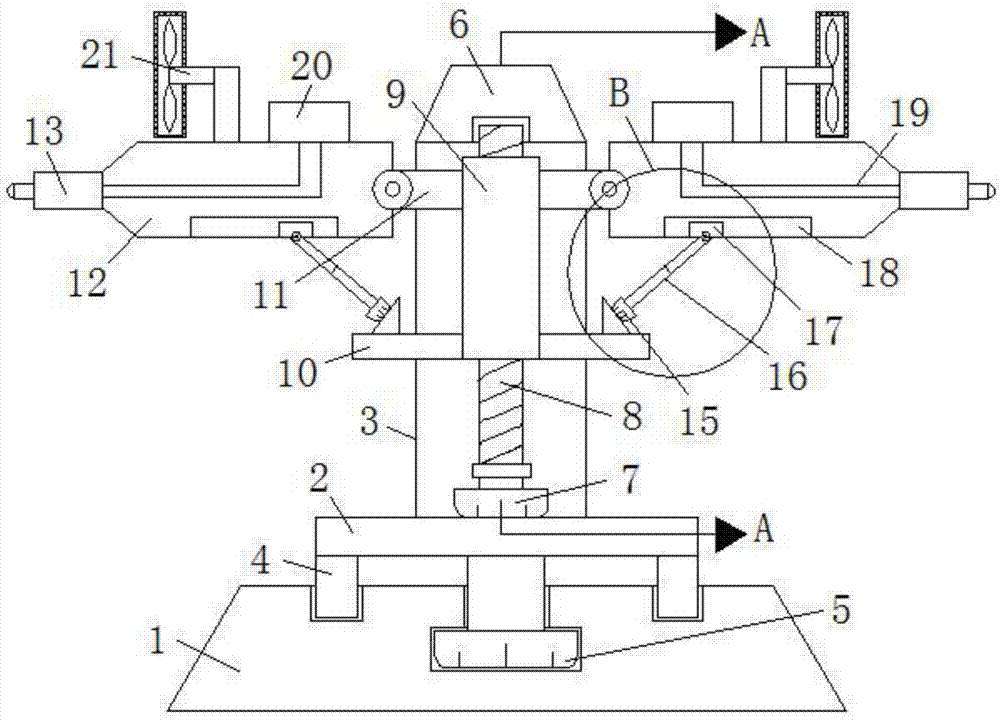
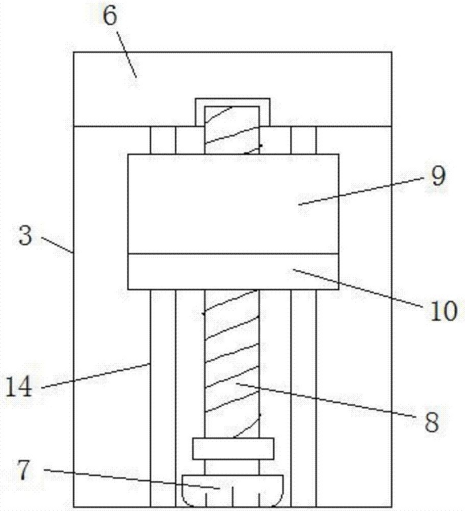
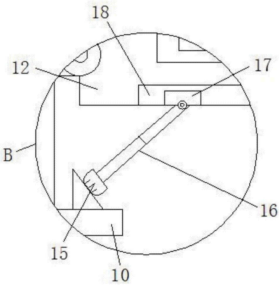
[0042] Such as figure 1 and 3 As shown, the present invention discloses a spraying industrial robot, including a base 1, a turntable 2, a fixed frame 3, an annular block 4, a first drive motor 5, a top cover 6, a second drive motor 7, a lead screw 8, Movable parts 9, fixed plate 10, connecting rod 11, mechanical arm 12, spray gun 13, the 3rd driving motor 15, telescoping rod 16, slide block 17, chute 18, spraying pipeline 19 and spraying box 20, wherein:

[0043] The upper end of...


PUM


Abstract

The invention discloses a spraying type industrial robot. The spraying type industrial robot comprises a base; annular clamping blocks are arranged on the base through annular clamping grooves, a rotary table is fixedly connected to the annular clamping blocks, the center of the bottom of the rotary table is connected with a first driving motor through a first rotary shaft, the first driving motor is fixed in an inner cavity of the base, a fixing frame is fixedly connected to the rotary table, a second driving motor is arranged at the bottom of the fixing frame, the second driving motor is connected with a coupler through a second rotary shaft, a threaded rod is arranged at the end, far away from the second rotary shaft, of the couple, the external of the threaded rod is screwed with a movable part, and connecting rods are symmetrically and fixedly connected to the two sides of the outer wall of the movable part; a mechanical arm is rotationally connected with the end, far away from the movable part, of each connecting rod; a spraying gun is arranged on the end, away from the corresponding connecting rod, of each mechanical arm, the end portion of each spraying gun communicates with a spraying pipeline, each spraying pipeline penetrates through the inner wall of the corresponding mechanical arm and extends outwards to communicate with a spraying box, fixing plates are symmetrically arranged on the two sides of the outer wall at the lower end of the movable part, an inclined block is fixedly connected to each fixing plate, a third driving motor is arranged on the outer side of each inclined block, each third driving motor is rotationally connected with a sliding block through a telescopic rod, and the lower side of the outer wall of each mechanical arm is provided with a sliding groove corresponding to the corresponding sliding block.

Description

technical field [0001] The invention relates to the technical field of industrial robots, in particular to a spraying industrial robot. Background technique [0002] Industrial robot is a kind of automation equipment with high degree of automation and work efficiency. Its work is controlled by pre-set programs and fixedly completes the same action. These industrial robots are widely used in automobile manufacturing, cutting, die-casting, and mold painting. , polishing, cargo handling, packaging and stacking and other fields. For repetitive work, the use of industrial robots can greatly reduce the labor intensity of workers and improve production efficiency, and as long as the procedures and machines do not fail, there will be no errors and quality problems in manual work. In addition, the most important thing is that the damage of industrial robots will not cause ethical and moral issues, which prevents the physical injury of workers during operation and greatly reduces med...

Claims


Application Information

Patent Timeline
Patent Type & Authority Applications(China)
IPC IPC(8): B05B13/04B05B15/08B05D3/04B05B15/68
CPCB05B13/0431B05D3/0406
Inventor 周信
Owner SUZHOU INST OF INDAL TECH
Why Eureka
Try Eureka