
A welding machine automatically travels on a guide rail

A technology of automatic walking and welding machine, which is applied in welding equipment, auxiliary welding equipment, welding/cutting auxiliary equipment, etc. The effect of adjustable tension and simple operation

Active Publication Date: 2019-01-01
CHENGDU XIONGGU JIASHI ELECTRICAL
View PDF9 Cites 0 Cited by
  • Summary
  • Abstract
  • Description
  • Claims
  • Application Information

AI Technical Summary

Problems solved by technology

[0004] The purpose of the present invention is to overcome the deficiencies of the prior art, and the purpose is to provide a welding machine automatic walking system on the guide rail to solve the problems of unstable walking and inconvenient operation of the welding machine

Method used


Image

  • A welding machine automatically travels on a guide rail
  • A welding machine automatically travels on a guide rail
  • A welding machine automatically travels on a guide rail

Examples


Embodiment 1

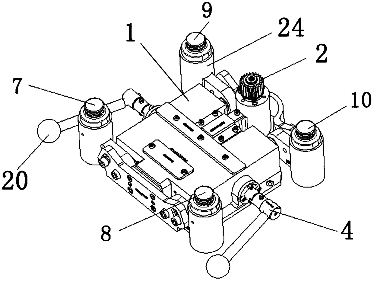
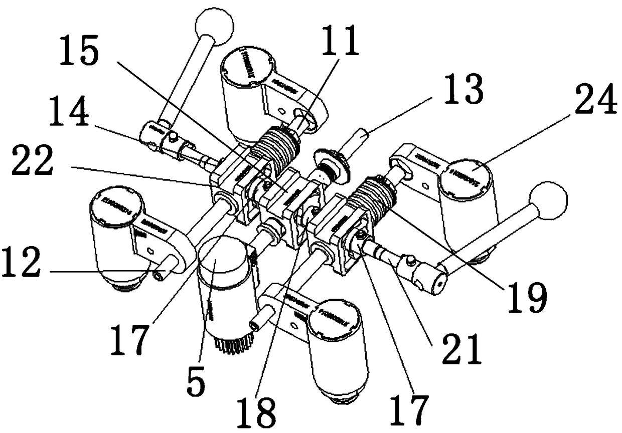
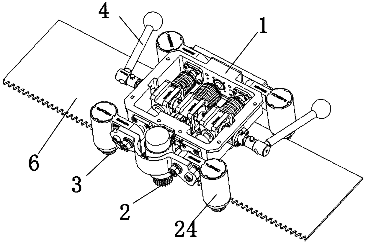
[0035] Such as Figure 1-8 As shown, a welding machine automatic walking system on the track of the present invention includes a walking frame 1, a driving wheel 2, a guide wheel 3, an adjustment handle 4, a motor 5 and a guide rail 6, and the walking frame 1 is the supporting structure of the entire automatic walking system. The other components are installed on the walking frame 1 to realize the automatic walking function of the welding machine along the guide rail 6. The guide wheel 3 is divided into the left front guide wheel 7, the left rear guide wheel 8, the right front guide wheel 9 and the right rear guide Wheel 10, the left front guide wheel 7 and the left rear guide wheel 8 are arranged on the front and rear of the walking frame 1 left side, the left front guide wheel 7 and the left rear guide wheel 8 are fixedly installed on the walking frame by the first guide shaft 11 respectively. 1 On the left side, the left front guide wheel 7 and the left rear guide wheel 8 a...

Embodiment 2

[0043] Such as Figure 1-8 As shown, a welding machine automatic walking system on the track of the present invention, on the basis of Embodiment 1, a return spring 19 is provided on the left side of the guide wheel slider 22, and under the control of the adjustment handle 4, the guide wheel slider 22 It is separated from the guide rail 6 by the elastic force of the return spring 19 . The return spring 19 provided on the left side of the guide wheel slider 22 is sleeved on the first guide shaft 11 .

[0044] The left side of the driving wheel slider 15 is provided with a return spring 19 , and under the control of the adjustment handle 4 , the driving wheel slider 15 is separated from the guide rail 6 by the elastic force of the returning spring 19 . The return spring 19 provided on the left side of the driving wheel slider 15 is still sleeved on the third guide shaft 13, because the third guide shaft 13 is a through shaft, and the first guide shaft 11 and the second guide sh...


PUM


Abstract

The invention discloses a system allowing a welding machine to automatically walk on a guide rail. A left side front guide wheel and a left side rear guide wheel are fixedly mounted on the left side of a walking frame through a first guide shaft, the left side front guide wheel and the left side rear guide wheel are connected with the first guide shaft through an adjusting support, a right side front guide wheel and a right side rear guide wheel are movably mounted on the right side of the walking frame through a second guide shaft, the right side front guide wheel and the right side rear guide wheel are connected with the second guide shaft through an adjusting support, a driving wheel is movably mounted on the right side of the walking frame through a third guide shaft, and is controlled by a motor to rotate, guide wheel sliding blocks linked mutually are arranged on the second guide shaft, guide wheel sliding block adjusting grooves are formed in the guide wheel sliding blocks, driving wheel sliding blocks linked mutually are arranged on the third guide shaft, driving wheel sliding block adjusting grooves are formed in the driving wheel sliding blocks, and guide wheel control cams matched with the guide wheel sliding block adjusting grooves are arranged on an adjusting handle.

Description

technical field [0001] The invention relates to the technical field of welding machines, in particular to a welding machine automatic walking system on guide rails. Background technique [0002] All-position automatic welding of pipelines When the pipeline is relatively fixed, with the help of mechanical and electrical methods, the welding equipment drives the welding torch to move around the pipe wall along the weld seam, thereby realizing automatic welding. The all-position automatic welding machine can realize all-position welding of flat, vertical, horizontal and overhead welding and all-position welding of large pipelines. [0003] The all-position automatic welding machine consists of two parts: a welding trolley and a guide rail. The welding trolley is installed on the welding guide rail through a clamping mechanism, and drives the welding torch to make a circular motion along the outer diameter of the pipe wall. The swing mechanism, the lateral adjustment mechanism a...

Claims


Application Information

Patent Timeline
Patent Type & Authority Patents(China)
IPC IPC(8): B23K37/02
CPCB23K37/0247
Inventor 刘碧清
Owner CHENGDU XIONGGU JIASHI ELECTRICAL
Learn More