
Novel PPR pipe heat melting welding equipment

A new type of hot-melt welding technology, which is applied in the field of new-type PPR pipe hot-melt welding equipment, can solve the problems of easily scalded staff and affect work efficiency, and achieves convenient model replacement, simple installation and removal process, and simple device structure Effect

Active Publication Date: 2017-11-07
YONGGAO CO LTD
View PDF4 Cites 0 Cited by
  • Summary
  • Abstract
  • Description
  • Claims
  • Application Information

AI Technical Summary

Problems solved by technology

[0002] With the development of the times, many PPR pipes have replaced traditional iron pipes in both household and industry nowadays. PPR pipes can provide hot or cold water to pass through and have a long service life. PPR pipes are generally welded by a hot melt machine. In order to adapt to PPR tubes of different sizes and models, usually the hot-melt die head on the head of the hot-melt machine can be replaced. Threaded rods are set on the left and right sides, and the threaded holes matching the threaded rods on the machine head are set on the hot-melt touch head for threaded connection. In this way, since the hot-melt touch head is always in a high temperature state during the working process, the hot-melt The die head dissipates heat, and the head of the hot-melt machine is an electrical device that cannot be directly heated by water. It can only wait for the hot-melt die head to cool down slowly, which will affect the work efficiency, or use other tools to turn the hot-melt die head down. Operation and maintenance, careless easy to burn the staff

Method used


Image

  • Novel PPR pipe heat melting welding equipment
  • Novel PPR pipe heat melting welding equipment
  • Novel PPR pipe heat melting welding equipment

Examples


Embodiment Construction

[0015] All features disclosed in this specification, or steps in all methods or processes disclosed, may be combined in any manner, except for mutually exclusive features and / or steps.

[0016] Any feature disclosed in this specification (including any appended claims, abstract and drawings), unless expressly stated otherwise, may be replaced by alternative features which are equivalent or serve a similar purpose. That is, unless expressly stated otherwise, each feature is one example only of a series of equivalent or similar features.

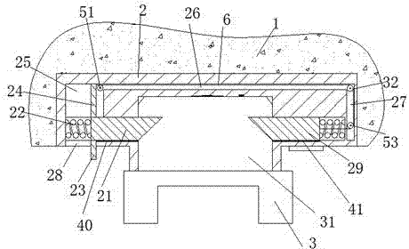
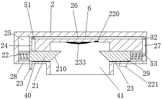
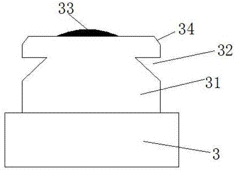
[0017] Such as Figure 1-Figure 4 As shown, a new type of PPR pipe hot-melt welding equipment of the present invention includes a disassembly base 2 fixedly arranged in the head 1 of the hot-melt machine and a hot-melt die head 3, and the upper end of the hot-melt die head 3 is fixed An engaging part 31 is provided, the top of the engaging part 31 is provided with a heat conduction terminal 33, and the two sides of the engaging part 31 are al...


PUM


Abstract

The invention discloses novel PPR pipe heat melting welding equipment which comprises a disassembly and assembly base and a heat melting die head which are fixedly arranged in a machine head of a heat melting machine; a clamping part is fixedly arranged at the upper end of the heat melting die head; a heat-conducting terminal is arranged at the top end of the clamping part; locking grooves are formed in the two side surfaces of the clamping part; a clamping groove clamped with the clamping part is formed in the middle point of the disassembly and assembly base; a heating terminal is arranged at the top wall of the clamping groove; a left sliding connection groove and a right sliding connection groove are symmetrically formed in the two sides of the disassembly and assembly base; the left sliding connection groove and the right sliding connection groove communicate with the clamping groove; a left locking pin and a right locking pin are respectively arranged in the left sliding connection groove and the right sliding connection groove; a left sliding rail and a right sliding rail are respectively arranged at the lower end wall of the left locking pin and the lower end wall of the right locking pin, and are respectively matched with the left locking pin and the right locking pin.

Description

technical field [0001] The invention relates to the field of welding technology, in particular to a novel PPR pipe hot-melt welding equipment. Background technique [0002] With the development of the times, many PPR pipes have replaced traditional iron pipes in both household and industry nowadays. PPR pipes can provide hot or cold water to pass through and have a long service life. PPR pipes are generally welded by a hot melt machine. In order to adapt to PPR tubes of different sizes and models, usually the hot-melt die head on the head of the hot-melt machine can be replaced. Threaded rods are set on the left and right sides, and the threaded holes matching the threaded rods on the machine head are set on the hot-melt touch head for threaded connection. In this way, since the hot-melt touch head is always in a high temperature state during the working process, the hot-melt The die head dissipates heat, and the head of the hot-melt machine is an electrical device that can...

Claims


Application Information

Patent Timeline
Patent Type & Authority Applications(China)
IPC IPC(8): B29C65/18B29C65/20
Inventor 黄常宇
Owner YONGGAO CO LTD
Learn More