Automatic stacking equipment for metal drums

An automatic stacking and metal bucket technology, applied in the field of stacking equipment, can solve the problems of increasing equipment cost and occupying space, limited length of paper pads, waste of manpower, etc.

Active Publication Date: 2017-11-07
汕头市澄海区正益设备有限公司
View PDF6 Cites 7 Cited by
  • Summary
  • Abstract
  • Description
  • Claims
  • Application Information

AI Technical Summary

Problems solved by technology

In the prior art, it is difficult to balance both the orientation of the barrel wall and the orientation of the handle
[0010] Second, according to the existing stacking method, the paper pads can only be inserted manually, and it is difficult to use an automatic paper feeding mechanism
This is because, when the paper is jammed, the mouth of the barrel faces upward, the position of the upper metal barrel is temporarily fixed and the lower metal barrel moves vertically, and the length of the paper pad is limited, so if the paper strip 73 and the paper feeding mechanism 7 are arranged on the upper Next to the metal barrel 8, such as image 3 As shown, after the lower metal barrel moves upwards, due to the shape factor of the paper strip 73 and the local turbulent airflow factor caused by the upward movement of the lower metal barrel 8, the paper strip 73 is likely to be squeezed out of the lower metal barrel and cannot be guided smoothly. Enter into the interior of the lower metal barrel 8 barrel cavity, such as Figure 4 Shown; On the contrary, if paper strip 73 and paper feeding mechanism 7 are fixed on the next side of lower metal bucket, as Figure 5 As shown, although the paper strip 73 can fall into the inside of the lower metal barrel cavity in advance before being folded, as shown in FIG. Figure 5 As shown, but after the lower metal barrel moved upwards, the paper strip 73 would also be discarded outside the lower metal barrel, as Image 6 shown
Due to the above reasons, the existing stacking method can only manually insert paper pads from both sides, which wastes manpower and is slow;
[0011] 3. According to the existing stacking method, the stacking speed is slow. This is because: each time a new metal barrel is stacked, the barrel holding block must go through a cycle of horizontal opening, vertical falling, horizontal entanglement, and vertical rising The action process, and the barrel support board must also go through the action process of rising and then falling, and loading the next metal barrel
Due to the slow stacking speed, it cannot keep up with the speed of other stations in the entire production line
In order to increase the production speed, the existing stacking equipment can only adopt a double-channel design, which increases equipment cost and occupies space

Method used


Image

  • Automatic stacking equipment for metal drums
  • Automatic stacking equipment for metal drums
  • Automatic stacking equipment for metal drums

Examples


Embodiment Construction

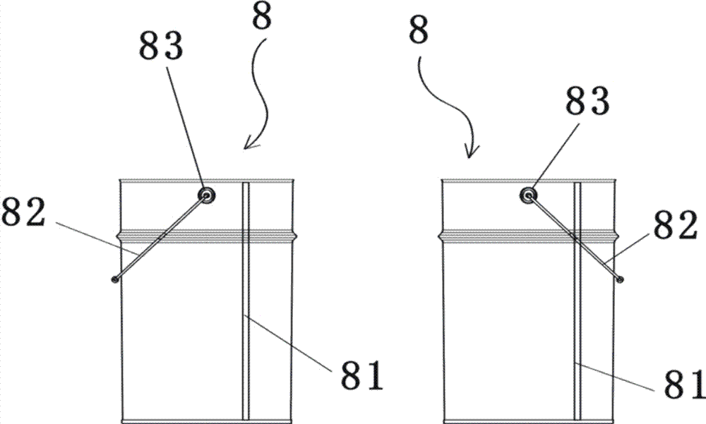
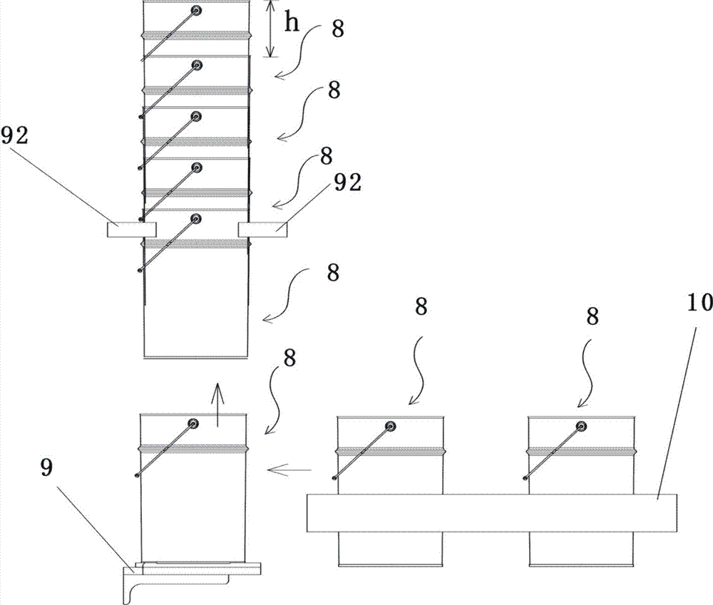
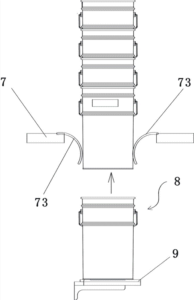
[0056] Figure 7 , Figure 8 , Figure 9 As shown, the metal barrel automatic stacking equipment includes a circumferential arrangement mechanism, a barrel support plate 9 for holding up the metal barrel stack, and a vertical drive mechanism for the barrel support plate to drive the vertical movement of the barrel support plate. The bucket stave vertical driving mechanism is a vertical chain 91, and the bucket support plate 9 is driven by the vertical chain 91 to move vertically, and the sprocket wheel of the vertical chain 91 is driven by a forward and reverse motor.

[0057] Figure 10 As shown, the circumferential finishing mechanism 1 includes a rotating base 11 and a sensor 12 for identifying circumferential markers on the barrel wall. The sensor 12 is installed on the periphery of the space above the rotating base 11; the rotating base 11 is driven by a servo motor 13, and the rotating shaft 14 of the rotating base For vertical, the sensor 12 is connected to a servo m...


PUM


Abstract

Automatic stacking equipment for metal drums comprises a circumferential arranging mechanism and a drum supporting plate used for supporting a metal drum stack. A first-grade turnover mechanism is arranged in front of the drum supporting plate. A horizontal delivery mechanism for delivering metal drums which are not stacked is arranged between the circumferential arranging mechanism and the first-grade turnover mechanism. A second horizontal clamping and delivering mechanism is arranged in front of the first-grade turnover mechanism. A second-grade turnover mechanism is arranged in front of the second horizontal clamping and delivering mechanism. The first-grade turnover mechanism comprises a first magnet block capable of rotating, and a rotary shaft of the first magnet block extends in the left-right direction. The first-grade turnover mechanism is further provided with a first-grade turnover power component for driving the first magnet block to rotate clockwise. The drum supporting plate is located below a second-grade blocking component. By means of the automatic stacking equipment for the metal drums, the stacking speed can be improved, the automatic paper-feeding mode can be adopted, and it is ensured that the directions of handles are coincident after stacking.

Description

technical field [0001] The invention belongs to the technical field of stacking equipment, and in particular relates to an automatic stacking equipment for metal drums. Background technique [0002] The side wall of the metal barrel 8 is generally formed into a cylinder by curling and welding the end to the end of the metal plate, so the side wall has a vertical weld 81, such as figure 1 As shown, the vertical weld is coated with a protective oil layer, and the color is quite different from that of the adjacent parts. The metal drum 8 generally also has a handle 82 (also known as a handle) and two handles 83. The two handles 83 are fixed and welded symmetrically and protrude from the upper part of the side wall of the metal drum. The two ends of the handle are inserted into the handle respectively. Blind hole in the ear. The side wall of the metal barrel is generally also printed with a color printing pattern. [0003] After the metal barrels are made, they need to be sta...

Claims


Application Information

Patent Timeline
Patent Type & Authority Applications(China)
IPC IPC(8): B65G57/00B65G57/03B65G57/16
CPCB65G57/005B65G57/035B65G57/165
Inventor 黄锐彬林国阳陈伟亮
Owner 汕头市澄海区正益设备有限公司
Why Eureka
Try Eureka