Trigger switch

A technology for triggering switches and contacts, applied in electrical switches, electrical components, circuits, etc., can solve the problem of not fundamentally solving contact sparks and reducing contact contact sparks.

Inactive Publication Date: 2017-11-07
李欣钊
View PDF7 Cites 0 Cited by
  • Summary
  • Abstract
  • Description
  • Claims
  • Application Information

AI Technical Summary

Problems solved by technology

The National Patent Office has disclosed the patent CN200810066620 double-contact switch technology. This technology is essentially a mechanical way to reduce contact sparks, and does not fundamentally solve the cause of contact sparks generated by contact contacts.

Method used


Image

  • Trigger switch
  • Trigger switch

Examples


Embodiment Construction

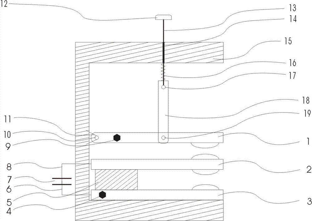
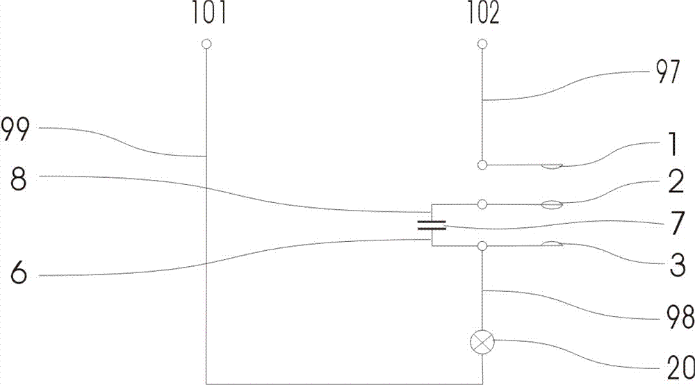
[0024] Now refer to the attached figure 1 And attached figure 2 , in combination with specific embodiments, the description is as follows: a trigger switch according to the present invention includes a moving contact 1, a pre-closed contact 2, a static contact 3, a static contact terminal 4, an elastic insulating support 5, a capacitor A side lead wire 6, capacitor 7, capacitor B side lead wire 8, movable contact terminal 9, movable contact housing hinge hole 10, hinge bracket 11, button 12, button insulating connecting rod 13, button connecting rod movable hole 14, Housing 15, spring 16, button connecting rod link reaming hole 17, moving contact connecting body 18, moving contact intermediate link reaming hole 19, load 20, lead wire 97 from power supply to moving contact terminal, static contact terminal Lead wire 98 to load B side, lead wire 99 from load A side to power supply, power supply A terminal 101, power supply B terminal 102.

[0025]The housing 15 is C-shaped as...


PUM


Abstract

A trigger switch comprises a moving contact, a pre-closing contact, a fixed contact, a fixed contact binding post, an elastic insulation support, a capacitor A side lead, a capacitor, a capacitor B side lead, a moving contact binding post, a moving contact shell hinged hole, a hinged support, a button, a button insulation connecting rod, a button connecting rod movable hole, a shell, a spring, a button connecting rod hinged hole, a moving contact connecting body, a moving contact middle hinged hole, a load, a lead from a power source to the moving contact binding post, a lead from the fixed contact binding post to a load B side, a lead from the load A side to the power source, a power source A binding post and a power source B binding post. According to the trigger switch, on the basis of the capacitor capacitive reactance formula that Xc=1 / 2 pi fc, by means of the voltage reduction current limitation principle of the capacitor, the contact voltage of the contacts is lowered fundamentally, so that the contact electric spark strength is lowered, and contact points are protected.

Description

technical field [0001] The invention relates to the technical field of jog switches, in particular to a trigger switch. Background technique [0002] In power control applications, electrical components such as switches and contactors are usually used to control the on-off of the current. The contact resistance of the connected and disconnected contacts increases due to electric sparks. The larger the electric sparks, the easier it is to cause the contact surface Resistance is generated, and this spark even burns out the contacts, causing the circuit to malfunction. The National Patent Office has disclosed the patent CN200810066620 double-contact switch technology, which is essentially a mechanical way to reduce contact sparks, and does not fundamentally solve the cause of contact sparks generated by contact contacts. [0003] According to the characteristics of the capacitor, the present invention utilizes the voltage-reducing and current-limiting principle of the capacito...

Claims


Application Information

Patent Timeline
Patent Type & Authority Applications(China)
IPC IPC(8): H01H9/30H01H9/38
Inventor 李欣钊
Owner 李欣钊
Why Eureka
Try Eureka