Grounding device and installation method of substation with cable inlet and outlet

A technology for grounding devices and substations, applied in substation grounding layout, switchgear, electrical components, etc., can solve the problems of reducing grounding resistance, increasing project implementation costs, and unsatisfactory results proved by practice

Active Publication Date: 2017-05-24
SHANGHAI ELECTRIC POWER DESIGN INST
View PDF1 Cites 0 Cited by
  • Summary
  • Abstract
  • Description
  • Claims
  • Application Information

AI Technical Summary

Problems solved by technology

[0002] For substations with cable inlet and outlet lines, if the soil resistivity of the substation site and surrounding areas is high, the ordinary grounding design cannot meet the requirements of the specification (GB 50065-2011 "Code for Grounding Design of AC Electrical Installations", the same below), It is usually used to increase the laying of dense grid-like grounding grids in the station to increase the shunt of short-circuit current and reduce grounding resistance. If the step voltage or contact voltage does not meet the requirements in a specific area, it may be necessary to lay gravel To improve insulation and ensure personal safety, these two methods will increase the cost of project implementation, and the practice has proved that the effect is not ideal

Method used


Image

  • Grounding device and installation method of substation with cable inlet and outlet
  • Grounding device and installation method of substation with cable inlet and outlet
  • Grounding device and installation method of substation with cable inlet and outlet

Examples


Embodiment 1

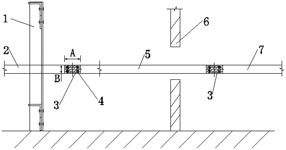
[0019] In this example, refer to figure 1 As shown, a substation grounding device with cable inlet and outlet lines includes a cable trench support grounding flat steel 2 that runs through the cable trench support column 1, and an indoor lead that is locked and connected to the cable trench support grounding flat steel 2 through the first screw 4. The flat steel 5, and the indoor grounding main line 7 locked and connected to the indoor connecting flat steel 5 through the first screw 4, and the grounding flat steel 2 arranged between the cable trench support and the indoor connecting flat steel 5, and the indoor connecting flat Tin layer 3 is applied to the overlapping area between steel 5 indoor grounding trunk lines 7 .

[0020] The distance A of the length A of the tin-plated layer 3 in the overlapping area is greater than or equal to twice the distance B of the width B.

[0021] The first screw 4 is a 12*16 type screw.

[0022] The second screw 9 is an M6*16 screw.

[00...

Embodiment 2

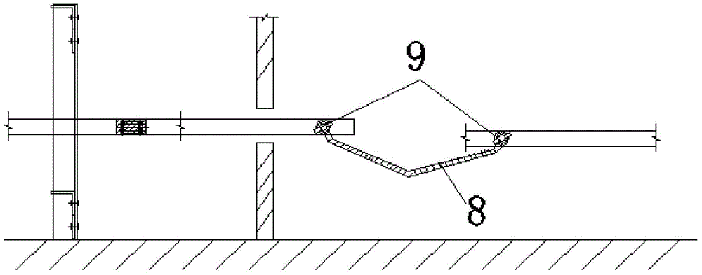
[0025] In this example, refer to figure 2 As shown, the difference from the first embodiment is that the indoor lead flat steel 5 and the indoor grounding trunk line 7 are connected by an indoor copper stranded wire 8 .

[0026] It includes the following steps: 1), cable trench support grounding flat steel 2 penetrates the cable trench support column 1, and indoor connecting flat steel 5 penetrates the outer wall 6 of the substation; 2), then cable trench supporting grounding flat steel 2 and indoor leading flat steel 5. Use 4 first bolts 4 for crimping; 3), then connect the indoor grounding trunk line 7 with the indoor copper stranded wire 8 on one side of the flat steel 5 indoors, and fix it with the second screw; The connection between the bracket grounding flat steel 2 and the indoor lead flat steel 5, and the connection between the indoor lead flat steel 5 and the indoor grounding trunk line 7 are provided with a tin-plated layer 3 in the overlapping area; 5), bolts cann...

Embodiment 3

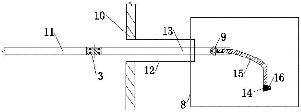
[0028] In this example, refer to image 3 As shown, the difference from Embodiment 1 is that the grounding device of the substation containing the cable inlet and outlet lines includes the grounding trunk line 11 in the piping room, and the grounding flat steel in the piping room that is connected to the grounding trunk line 11 in the piping room through the first screw 4. 13, and the row pipe copper strand 15 fixedly connected with the ground flat steel 13 in the row pipe through the second screw 9, and the exothermic welding joint 14 fixed on the row pipe copper strand 15, and fixed on the exothermic welding joint 14 ground electrode 16 at one end.

[0029] It includes the following steps: 1), the grounding flat steel 13 in the row pipe runs through the outer wall 10 of the substation and the row pipe 12, the grounding trunk line 11 in the row pipe room is locked by the first screw 4 to the grounding flat steel 13 in the row pipe, and the overlapping area is set at the conne...


PUM


Abstract

The invention provides a grounding device of a transformer substation containing inlet and outlet cables. The grounding device comprises cable trench support flat steel, indoor leading flat steel, an indoor grounding main line and overlap region tin coatings, wherein the cable trench support flat steel penetrates through a cable trench support stand column, the indoor leading flat steel is in locked connection with the cable trench support flat steel through a first screw, the indoor grounding main line is in locked connection with the indoor leading flat steel through a first screw, and the overlap region tin coatings are arranged between the cable trench support flat steel and the indoor leading flat steel and between the indoor leading flat steel and the indoor grounding main line. The invention discloses the grounding device of the transformer substation containing inlet and outlet cables and a mounting method of the grounding device. According to the invention, since flat steel or a copper stranded wire is used for connecting the grounding device in a cable structure with a transformer substation grounding network, the grounding device in the cable structure can be used for shunting the transformer substation grounding network, thereby reducing the total ground resistance, further reducing the earth current of the transformer substation grounding network and lowering the contact voltage and step voltage of the transformer substation.

Description

technical field [0001] The invention relates to the field of electric equipment, in particular to a grounding device and an installation method for a substation with cable inlet and outlet lines. Background technique [0002] For substations with cable inlet and outlet lines, if the soil resistivity of the substation site and surrounding areas is high, the ordinary grounding design cannot meet the requirements of the specification (GB 50065-2011 "Code for Grounding Design of AC Electrical Installations", the same below), It is usually used to increase the laying of dense grid-like grounding grids in the station to increase the shunt of short-circuit current and reduce grounding resistance. If the step voltage or contact voltage does not meet the requirements in a specific area, it may be necessary to lay gravel To improve insulation and ensure personal safety, these two methods will increase the cost of project implementation, and the practice has proved that the effect is n...

Claims


Application Information

Patent Timeline
Patent Type & Authority Patents(China)
IPC IPC(8): H02B5/01H02B3/00
CPCH02B3/00H02B5/01
Inventor 褚强关雪飞姜波何仲孟毓
Owner SHANGHAI ELECTRIC POWER DESIGN INST
Why Eureka
Try Eureka