
A locking structure for connector fitting insertion

A locking structure and connector technology, which is applied to the parts, connections, electrical components and other directions of the connecting device, can solve the problems of inability to directly insert and pull out, inapplicability, etc., and achieve the effects of convenient operation, compact structure and small volume.

Pending Publication Date: 2017-11-07
苏州丰年科技股份有限公司
View PDF3 Cites 2 Cited by
  • Summary
  • Abstract
  • Description
  • Claims
  • Application Information

AI Technical Summary

Problems solved by technology

The common male and female pairs are plugged in. In order to prevent the connection between the two from loosening, a locking structure is provided outside the rubber core. The locking structure is generally threaded and buckled, but neither of them is quick insertion. The first choice of connection, the former needs to rotate the nut to achieve the purpose of locking or unlocking, and cannot be directly plugged in; the latter can be directly plugged in when inserted, but when unlocking and pulling out, it is necessary to use tools such as a screwdriver to withdraw the deadbolt from the lock The lock can only be unlocked through the holes, and it is not suitable for devices that need to be quickly plugged and unplugged. For example, the connection of control signal devices often requires the operator to quickly plug and unplug the connecting wires of various functional signals.

Method used


Image

  • A locking structure for connector fitting insertion
  • A locking structure for connector fitting insertion
  • A locking structure for connector fitting insertion

Examples


Embodiment 1

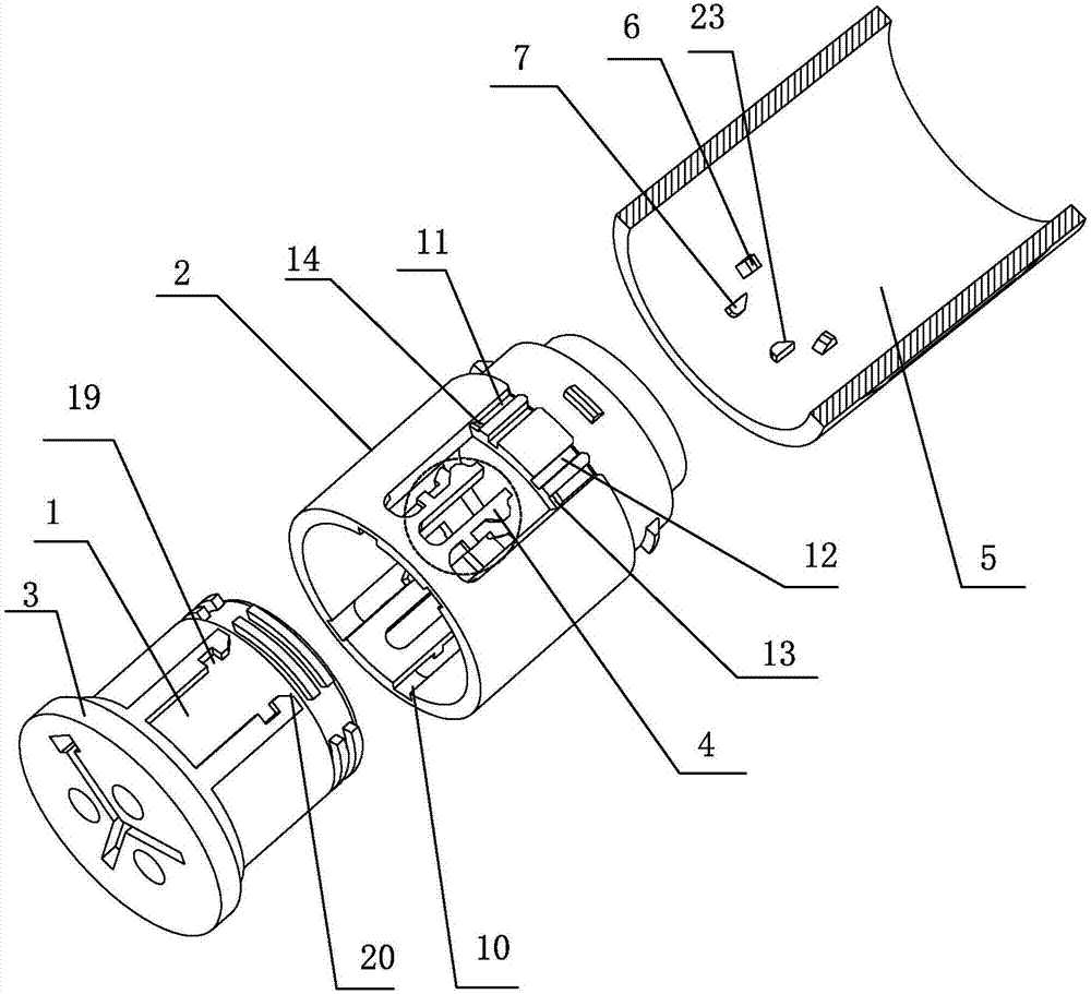
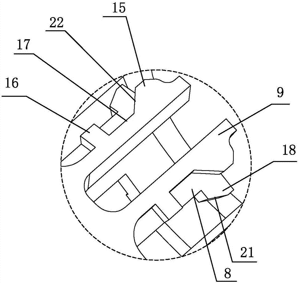
[0028] Embodiment one: see Figure 1~5 As shown, a locking structure for inter-plugging connectors, including a slot mechanism 1 arranged on the male or female rubber core, and an elastic buckle component set on the female rubber core 2 or the male rubber core 3 4, and the locking sleeve 5 sleeved outside the rubber core where the elastic buckle component 4 is located, the inner wall of the locking sleeve 5 is provided with a snap-fit ​​connection with the rubber core where the elastic buckle component 4 is located A pair of anti-falling ribs 6, and a pair of pushing bosses 7 that cooperate with the elastic buckle assembly 4, the elastic buckle assembly 4 is a high and low double-layer U-shaped shrapnel, and the low-level shrapnel 8 is connected to the buckle The groove mechanism 1 is snap fit, and the high-level shrapnel 9 is snap fit with the pushing boss 7 .

[0029] Such as figure 1 As shown, the inner wall of the rubber core where the elastic buckle component 4 is loca...


PUM


Abstract

The invention discloses a locking structure for connector fitting insertion. The locking structure is characterized in that the structure comprises a clamping slot mechanism arranged on a male end rubber core or a female end rubber core, an elastic buckling component arranged on the female end rubber core or the male end rubber core and a lock sleeve which sleeves the outside of the rubber core where the elastic buckling component is located, wherein a pair of anti-drop convex ribs connected with the rubber core where the elastic buckling component is located are arranged on the inner wall of the lock sleeve; and a pair of pushing bosses cooperating with the elastic buckling component is also arranged on the inner wall of the lock sleeve. The elastic buckling component is a high and low double-layer U-shaped spring sheet; the spring sheet of the lower layer is inserted and matched with the slot mechanism; and the spring sheet of the upper layer is matched with the pushing bosses in a buckled and inserted mode. According to the locking structure for connector fitting insertion, through cooperation between the elastic buckling component and the lock sleeve, rapid insertion and pulling between the male and the female rubber cores are realized; no tool needs to be used; and the operation is convenient and fast.

Description

technical field [0001] The invention relates to the technical field of electrical connectors, in particular to a locking structure for mating connectors. Background technique [0002] Connectors are an indispensable part of electronic equipment and an important bridge between the bus and branch lines, blocked and isolated circuits. In ensuring the continuous and reliable operation of the equipment, the primary requirement for the connector is that the connection relationship is stable and not easy to disengage; at the same time, these plugs and sockets (or male and female ends) usually need to be used for a long time, and the connector is required to be strong and durable. , Waterproof and dustproof, suitable for various outdoor harsh environments. [0003] Usually, the plug-in connector includes a male end 25 and a female end 26. After the two are plugged together, the inner rubber core is connected. The conventional rubber core generally includes an inner rubber core and ...

Claims


Application Information

Patent Timeline
IPC IPC(8): H01R13/627H01R13/633
CPCH01R13/6275H01R13/633
Inventor 叶超
Owner 苏州丰年科技股份有限公司
Learn More