
Multi-vibrator piezoelectric wind energy capturing device

A trap and piezoelectric technology, applied in piezoelectric effect/electrostrictive or magnetostrictive motors, electrical components, generators/motors, etc., can solve the problem of damage to piezoelectric vibrators, difficulty in driving blades to rotate for power generation, structural complex and other issues, to achieve the effect of strong power generation capacity, simple structure, and improved reliability

Active Publication Date: 2017-11-07
ZHEJIANG NORMAL UNIVERSITY
View PDF2 Cites 4 Cited by
  • Summary
  • Abstract
  • Description
  • Claims
  • Application Information

AI Technical Summary

Problems solved by technology

Most of the existing piezoelectric wind energy collectors are rotary, that is, the blades are firstly rotated by the wind, and then the blades drive the rotating shaft to excite the piezoelectric vibrator to generate electricity. In addition to the complex structure and the need for mechanical parts to switch motions, this type of generator has a high wind speed. When it is low, it is difficult to drive the blades to rotate to generate electricity, and the piezoelectric sheet is subjected to alternating tensile and compressive stress during operation, and the piezoelectric vibrator is easily damaged due to excessive tensile stress

Method used


Image

  • Multi-vibrator piezoelectric wind energy capturing device
  • Multi-vibrator piezoelectric wind energy capturing device

Examples


Embodiment Construction

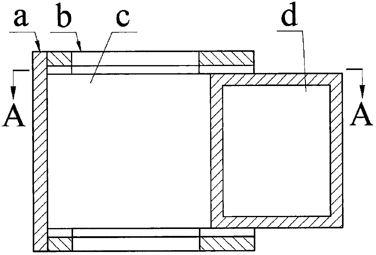
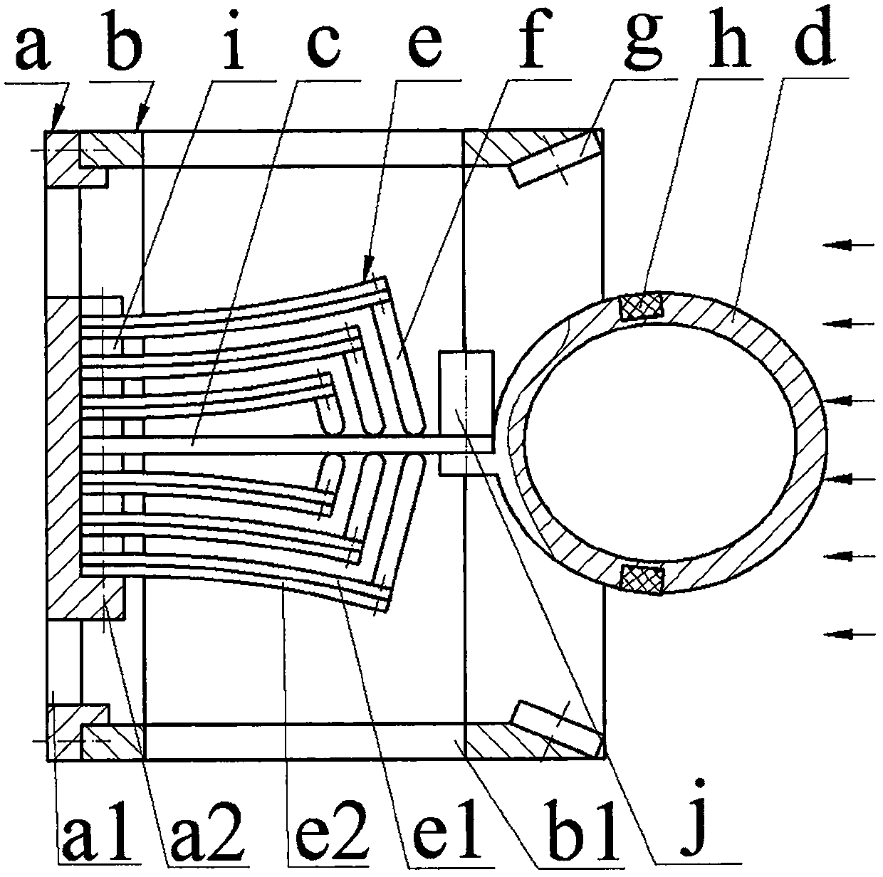
[0008] Each side wall of the housing b is provided with a flow hole b1, and one end of the housing b is installed with a vertical plate a through screws. Install piezoelectric vibrator e and elastic reed c, the number of piezoelectric vibrators e on both sides of elastic reed c is equal, between elastic reed c and its adjacent piezoelectric vibrator e, between two adjacent piezoelectric vibrators e Spacers i are crimped between them; the piezoelectric vibrator e is bonded by the substrate e1 and the piezoelectric sheet e2, and the substrate e1 is installed close to the elastic reed c; the non-fixed end of the piezoelectric vibrator e is installed with a top block f via screws , the top block f is installed on one side of the substrate e1 of the piezoelectric vibrator e, and the non-fixed end of the top block f leans against the elastic reed c; the non-fixed end of the elastic reed c is installed with a mass j and an ellipse The disturbing body d is a hollow structure, and two ...


PUM


Abstract

The invention relates to a multi-vibrator piezoelectric wind energy capturing device and belongs to the field of fluid power generation. Each side wall of a housing is provided with a flow passage hole; one end of the housing is equipped with a vertical plate provided with a flow passage hole and a raised bench; the raised bench is equipped with piezoelectric vibrators and an elastic reed; and each piezoelectric vibrator is formed by bonding a substrate and a piezoelectric sheet. The non-fixed end of each piezoelectric vibrator is provided with a push block; the non-fixed end of each push block is abutted against the elastic reed; the non-fixed end of the elastic reed is equipped with a mass block and a flow disturbance body; two moving magnets are symmetrically embedded in the flow disturbance body; the side walls of the housing are symmetrically provided with two static magnets; the moving magnets and the static magnets are in same magnetic pole opposite arrangement; and the geometric centers of moving magnets and static magnets are located on the same circumference. The piezoelectric vibrator is in a flat and straight structure before installation and in a bending structure after installation. The advantages are that self-excited vibration power generation is realized; fluid velocity and direction adaptability is high, and the structure is simple; each piezoelectric sheet only bears compressive stress, and reliability is high; and the multiple vibrators work synchronously, and power generating capability is high.

Description

technical field [0001] The invention belongs to the technical field of new energy and power generation, and in particular relates to a multi-vibrator piezoelectric wind energy capture device, which provides energy for wireless sensor nodes. Background technique [0002] Wind energy widely exists in nature, and wind power generation has become one of the mainstream energy sources in the world today. In the past, people only focused on the research of large-scale wind power generation systems. In recent years, with the maturity of wireless sensor network technology and its popularization in monitoring fields such as the environment, buildings, bridges, military and public safety, it is possible to provide continuous energy supply for it. The research on the miniature wind energy capture device has been widely concerned by scholars at home and abroad. The reason is that the energy of the chemical battery is limited, and its service time is far shorter than the life of the wirel...

Claims


Application Information

Patent Timeline
Patent Type & Authority Applications(China)
IPC IPC(8): H02N2/18
CPCH02N2/185H02N2/186Y02E10/72
Inventor 王淑云朱雅娜王成武
Owner ZHEJIANG NORMAL UNIVERSITY
Learn More