Automatic wall face positioning and grooving machine for indoor architectural decoration construction

An automatic positioning and slotting machine technology, applied in the direction of work accessories, manufacturing tools, stone processing tools, etc., can solve the problems of low labor intensity, low work efficiency, and wall slotting angle deviation

Inactive Publication Date: 2017-11-10
俞樑兵
View PDF0 Cites 7 Cited by
  • Summary
  • Abstract
  • Description
  • Claims
  • Application Information

AI Technical Summary

Problems solved by technology

[0003] In order to solve the above problems, the present invention provides a wall surface automatic positioning and slotting machine for indoor building decoration construction, which can solve the existing problems of low work efficiency, high labor intensity, and inability to adjust the level when manually slotting the wall surface. The position and the vertical position are positioned at the same time, the angle deviation will be generated when the groove is made on the wall, the debris splashed during the groove operation may hurt people, the inside of the groove cannot be effectively cleaned and the damage generated during the groove Debris is difficult to clean and other problems; it can realize the functions of positioning and scribing on the wall, positioning and slotting, and comprehensive cleaning in the slot. It has high work efficiency, low labor intensity, and can simultaneously position the horizontal position and the vertical position. There will be no angle deviation when grooving the wall, and the debris splashed during the grooving operation will be isolated by the side plate, which can effectively clean the opened groove and the debris generated during the grooving process will fall into the collection Advantages in the box

Method used


Image

  • Automatic wall face positioning and grooving machine for indoor architectural decoration construction
  • Automatic wall face positioning and grooving machine for indoor architectural decoration construction
  • Automatic wall face positioning and grooving machine for indoor architectural decoration construction

Examples


Embodiment Construction

[0029] In order to make the technical means, creative features, goals and effects achieved by the present invention easy to understand, the present invention will be further described below in conjunction with specific illustrations. It should be noted that, in the case of no conflict, the embodiments in the present application and the features in the embodiments can be combined with each other.

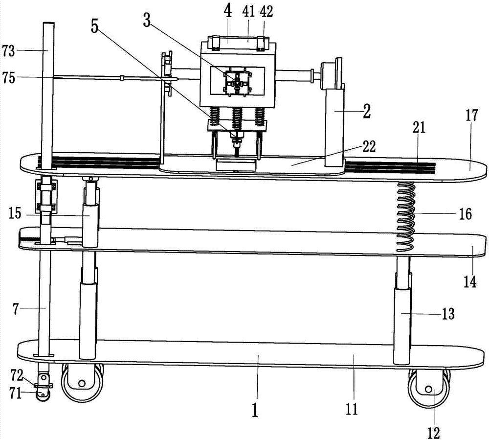
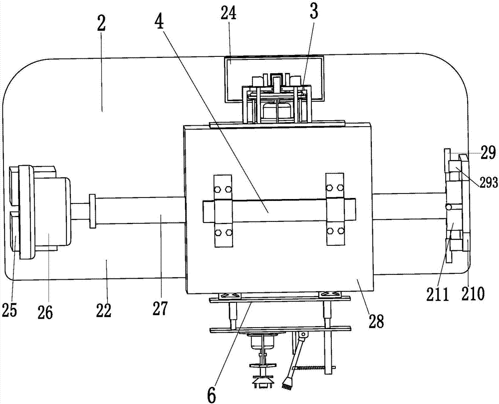
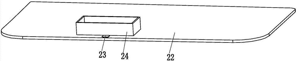
[0030] Such as Figure 1 to Figure 9 As shown, a wall automatic positioning slotting machine for indoor building decoration construction, including a walking lifting device 1, a moving rotating device 2, a marking device 3, a level device 4, a slotting device 5, a slot cleaning device 6 and an elevation device 7. The mobile rotating device 2 is installed on the top of the walking lifting device 1, the marking device 3, the level device 4, the slotting device 5, and the slot cleaning device 6 are all installed on the mobile rotating device 2, and the elevation device 7 is connected wi...


PUM


Abstract

The invention relates to a wall surface automatic positioning and slotting machine for indoor building decoration construction, which includes a walking lifting device, a moving and rotating device, a marking device, a level device, a slotting device, a slot cleaning device and an elevation device. The device is installed on the top of the walking lifting device, the marking device, the level device, the slotting device, and the cleaning device are all installed on the mobile rotating device, and the elevation device is connected with the walking lifting device. The present invention can solve the existing problems of angle deviation when grooving the wall surface manually, the hidden danger of injury caused by debris splashed during the grooving operation, and the difficulty of the debris generated during the grooving process. Difficulties such as cleaning; it can realize the functions of positioning and scribing on the wall, positioning and slotting, and comprehensive cleaning in the slot. It has the function of mechanized slotting on the wall without angle deviation, and the splashed debris during slotting operations will be caught by the side panels. The debris generated during the isolation and grooving process will fall into the collection box, etc. Advantages.

Description

technical field [0001] The invention relates to the field of wall surface slotting equipment, in particular to a wall surface automatic positioning slotting machine for indoor building decoration construction. Background technique [0002] In the decoration process, slotting to bury and lay wires and water pipes is the most common construction project. The traditional building decoration slotting process is to manually measure the wiring, cut two lines with a cutting saw, and then slot along the cut lines. , not only time-consuming and labor-intensive, the process is complicated, but also due to the poor stability of manual operation when the cutting saw cuts the line, the slotting accuracy is poor, the slotting effect is not good, and the debris splashed during the slotting operation has the potential to hurt people and cannot be split Effective cleaning is carried out in the grooves that have been passed, resulting in re-grooving operations where the grooves are not in pla...

Claims


Application Information

Patent Timeline
Patent Type & Authority Applications(China)
IPC IPC(8): B28D1/14B28D7/00B28D7/02
CPCB28D1/14B28D7/00B28D7/02
Inventor 俞樑兵
Owner 俞樑兵
Why Eureka
Try Eureka