Land tamping machine for building

A construction and land technology, applied in the field of construction land tamping machines, can solve the problems of laborious tamping devices, inability to ensure tamping accurately, high cost, etc.

Inactive Publication Date: 2017-11-10
金柯楠
View PDF0 Cites 14 Cited by
  • Summary
  • Abstract
  • Description
  • Claims
  • Application Information

AI Technical Summary

Problems solved by technology

Existing compaction and compaction mechanisms mostly use large-scale road rollers and manual electric impact compaction devices, and it is too costly for large-scale road rollers to compact small-scale local ground
[0003] The artificial electric impact ramming device is more often found in the ramming site of the construction site. The artificial electric impact ramming device needs to be rammed by the left and right movement of the human control device, and the ramming process is through the impact of the pressing surface at the lower end of the device. It is inevitable that the pressed part and the unpressed part of the edge of the tamping surface will be separated to form small potholes. It is not only labor-intensive but also time-consuming to move the tamping device continuously by manpower, and there will inevitably be errors in manual movement, and it cannot be accurately guaranteed that every place is tamped flat

Method used


Image

  • Land tamping machine for building
  • Land tamping machine for building

Examples


Embodiment Construction

[0016] The following will clearly and completely describe the technical solutions in the embodiments of the present invention with reference to the accompanying drawings in the embodiments of the present invention. Obviously, the described embodiments are only some, not all, embodiments of the present invention. Based on the embodiments of the present invention, all other embodiments obtained by persons of ordinary skill in the art without making creative efforts belong to the protection scope of the present invention.

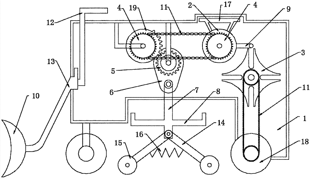
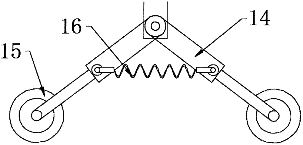
[0017] see Figure 1~2 , in the embodiment of the present invention, a ground tamping machine for construction includes a machine body 1; the machine body 1 is mainly composed of a driving wheel 2, a Maltese cross core 3, a sprocket 4 and a cam 6; the machine The upper end of the body 1 is fixedly connected to the base 17, and the lower end of the base 17 is rotatably connected to the driving wheel 2. The driving wheel 2 mainly provides the power source for ea...


PUM


Abstract

The invention discloses a ground tamping machine for construction, which comprises a machine body; the machine body is mainly composed of a driving wheel, a Maltese cross movement, a sprocket and a cam, the upper end of the machine body is fixedly connected to a base, and the lower end of the base is rotatably connected to drive The driving wheel is fixedly connected to the sprocket, and the edge of the driving wheel is fixedly connected to the lever. The lower end of the lever is set with a Maltese cross movement, the lower end of the Maltese cross movement is set with a moving wheel, and the left end of the driving wheel is set with an incomplete gear, which is fixed on the incomplete gear. Connect the sprocket, set the cam at the lower end of the incomplete gear, the cam is fixedly connected with the complete gear, the lower part of the cam rotates and connects to the hanging beam, the two ends of the hanging beam are hinged to the hydraulic telescopic rod, and the lower part of the hydraulic telescopic rod rotates to connect to the pressure roller. This device uses the pressure roller to flatten and tamp the ground. The pressure roller rolls to avoid the uneven marks caused by direct strong impact. The driving wheel drives the Maltese cross movement to move intermittently. When the machine body moves, the pressure roller shrinks. pressure.

Description

technical field [0001] The invention relates to a construction machine, in particular to a construction land tamping machine. Background technique [0002] During the construction process of construction projects, backfilling is often carried out after the foundation or foundation pit is dug deep, and the backfilled land usually needs to be compacted and flattened. Existing flattening and compacting mechanisms mostly use large-scale road rollers and manual electric impact compaction devices, and it is too expensive for large-scale road rollers to be used for compacting small-scale local ground. [0003] The artificial electric impact ramming device is more often found in the ramming site of the construction site. The artificial electric impact ramming device needs to be rammed by the left and right movement of the human control device, and the ramming process is through the impact of the pressing surface at the lower end of the device. It is inevitable that the pressed part...

Claims


Application Information

Patent Timeline
Patent Type & Authority Applications(China)
IPC IPC(8): E02D3/046E02D3/074E02F3/76E02F3/815
CPCE02D3/046E02D3/074E02F3/76E02F3/815
Inventor 金柯楠
Owner 金柯楠
Why Eureka
Try Eureka